


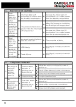


E.
Gas System
1.
Purge gas not
flowing
Control system will
activate an alarm
buzzer and
illuminate a
warning light on the
control panel
This alarm will continue until the
furnace is turned off and the 'purge'
gas supply is restored. While the alarm
is activated the control system will not
allow introduction of 'reducing' gas.
Faulty solenoid
valve or solenoid
coil connection
Investigate or contact Carbolite Gero
Faulty Relay (R2,
R4)
Investigate or contact Carbolite Gero
Pressure switch not
set at the correct
pressure
Investigate or contact Carbolite Gero
(do not tamper with pressure settings
as this may void warranty claims).
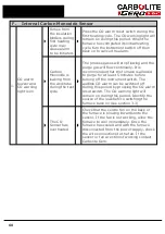
2.
Process gas
not flowing.
No indication
of gas flow
though the
flow meters.
Flow meter requires
adjustment
Adjust the flow rate to comply with
working standards
Faulty solenoid
valve or solenoid
coil connection
Investigate or contact Carbolite Gero
Gas oxidising/
reducing selector
switch faulty
Investigate or contact Carbolite Gero
Faulty Relay (R2)
Investigate or contact Carbolite Gero
Controller Logic
Faulty
Faulty controller, contact Carbolite
Gero
Pressure switch not
set at the correct
pressure
Investigate or contact Carbolite Gero
(do not tamper with pressure settings)
59
Содержание CARBOLITE GERO CAF G5
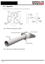
Страница 63: ...Fig 3 Front Tube Seal Assembly Fig 4 Door Arm Assembly 63 ...
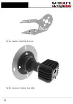
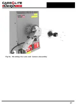
Страница 64: ...Fig 5a Camera Mounting Bracket Fig 5b Lens and Camera Assembly 64 ...
Страница 65: ...Fig 5c Sliding the Camera Mounting Bracket Assembly onto the Door Arm 65 ...
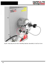
Страница 66: ...Fig 5d Securing the Camera Mounting Bracket Assembly to the Door Arm 66 ...
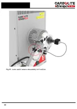
Страница 67: ...Fig 5e Mounting the Lens and Camera Assembly 67 ...
Страница 68: ...Fig 5f Lens and Camera Assembly in Position 68 ...
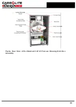
Страница 69: ...Fig 6a Rear View of the Standard CAF G5 Furnace Showing Brick Box Assembly 69 ...
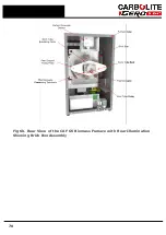
Страница 70: ...Fig 6b Rear View of the CAF G5 Biomass Furnace with Rear Illumination Showing Brick Box Assembly 70 ...
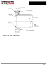
Страница 71: ...Fig 7 Front Tube Seal Position 71 ...
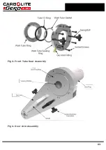
Страница 72: ...Fig 8 Tube End Seal Assembly Tightening Sequence Fig 9 Work Tube Front Support 72 ...
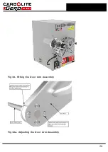
Страница 73: ...Fig 10 Fitting the Door Arm Assembly Fig 10a Adjusting the Door Arm Assembly 73 ...
Страница 74: ...Fig 11a Furnace Case and Controls 74 ...
Страница 75: ...Fig 11b Gas Inlet Pipe Fig 12 Positioning the Furnace 75 ...
Страница 76: ...Fig 13a Positioning Samples on the Sample Carrier Fig 13b Loading Samples into the Mouth of the Work Tube 76 ...
Страница 77: ...Fig 13c Loading Samples into the Work Tube 77 ...
Страница 78: ...Fig 16 File Folder 78 ...
Страница 79: ...Fig 17 Door Arm Assembly Exploded View 79 ...
Страница 82: ...SST DT HT FT Fig 18 Report Sheet Page 2 Side View Plan View Fig 19 Formed Wire Sample 82 ...
Страница 83: ...Fig 20 Sample Carrier Sample Tiles and Sample Positions 83 ...
Страница 84: ...Fig 21a Coal and Coke Test Piece Mould Fig 21b Biomass Test Piece Mould and Hand Press 84 ...
Страница 85: ...Fig 22 Sample Loading Tool Fig 23 Camera Ethernet Connection 85 ...
Страница 86: ...Fig 24 LED Driver Connection 86 ...
Страница 87: ...Notes Service Record Engineer Name Date Record of Work ...


