


Note:
The heating elements are fitted at the factory to test the furnace but are
removed for transit. These elements are extremely fragile, and can be damaged by
contamination: handle them with care and keep them clean. Avoid touching the heating
part.
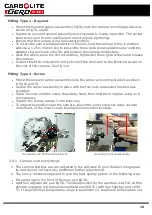
Slide one insulating collar over each element, then gently slide the element into its hole
in the furnace until the tip of the element locates in the front insulation, see fig 1. If the
element does not slide in freely check that you are holding it in line with the hole; it may
help to rotate the element whilst sliding it in. Only light finger pressure should be
required. When the element is in position slide the insulating collar up against the
furnace back insulation.
Use the braids to link the elements and connect them to the terminal posts as shown in
fig 1. Make sure the braids do not touch any other component, or each other.
3.3.2
Installing the Work Tube and Rear Seal Assembly
Ensure that the furnace is isolated from the mains supply, remove the back panel and
front panel from the furnace unit.
Remove the fixing nut and one washer from each of the work tube back support fixing
pillars on the back of the furnace. See fig 6a, 6b.
Take the rear insulation assembly. See Fig 2.
Carefully insert the work tube and back seal assembly into the furnace from the back
and slide it through the furnace until the work tube is protruding from the front. The
work tube is correctly positioned when: the work tube insulating collar is in contact with
the back face of the furnace heating chamber, the work tube back support is located
over the fixing posts and the thermocouple sheath is at the top above the vent tube
fitting. Secure the work tube back support in position using the fixings provided. See fig
6.
Note:
Take care not to stress the work tube. The work tube back support must be
parallel to the back of the furnace heating chamber and it should not be necessary to
bend the back support fixing posts to locate it.
Connect the numbered thermocouple leads to the thermocouple connecting terminals
mounted on the work tube back support. Ensure correct polarity, compensating cable
colour coding is:
thermocouple leg
colour
negative
white
positive
orange
Rear Lighting Option.
If the rear lighting option is fitted connect the 6 way socket and plug that connects the
LED lights to the LED Driver positioned in the bottom right of the case looking at the
rear of the unit, see fig 23.
Make sure the element braids do not touch any metal components of the back tube seal
assembly.
12
Содержание CARBOLITE GERO CAF G5
Страница 63: ...Fig 3 Front Tube Seal Assembly Fig 4 Door Arm Assembly 63 ...
Страница 64: ...Fig 5a Camera Mounting Bracket Fig 5b Lens and Camera Assembly 64 ...
Страница 65: ...Fig 5c Sliding the Camera Mounting Bracket Assembly onto the Door Arm 65 ...
Страница 66: ...Fig 5d Securing the Camera Mounting Bracket Assembly to the Door Arm 66 ...
Страница 67: ...Fig 5e Mounting the Lens and Camera Assembly 67 ...
Страница 68: ...Fig 5f Lens and Camera Assembly in Position 68 ...
Страница 69: ...Fig 6a Rear View of the Standard CAF G5 Furnace Showing Brick Box Assembly 69 ...
Страница 70: ...Fig 6b Rear View of the CAF G5 Biomass Furnace with Rear Illumination Showing Brick Box Assembly 70 ...
Страница 71: ...Fig 7 Front Tube Seal Position 71 ...
Страница 72: ...Fig 8 Tube End Seal Assembly Tightening Sequence Fig 9 Work Tube Front Support 72 ...
Страница 73: ...Fig 10 Fitting the Door Arm Assembly Fig 10a Adjusting the Door Arm Assembly 73 ...
Страница 74: ...Fig 11a Furnace Case and Controls 74 ...
Страница 75: ...Fig 11b Gas Inlet Pipe Fig 12 Positioning the Furnace 75 ...
Страница 76: ...Fig 13a Positioning Samples on the Sample Carrier Fig 13b Loading Samples into the Mouth of the Work Tube 76 ...
Страница 77: ...Fig 13c Loading Samples into the Work Tube 77 ...
Страница 78: ...Fig 16 File Folder 78 ...
Страница 79: ...Fig 17 Door Arm Assembly Exploded View 79 ...
Страница 82: ...SST DT HT FT Fig 18 Report Sheet Page 2 Side View Plan View Fig 19 Formed Wire Sample 82 ...
Страница 83: ...Fig 20 Sample Carrier Sample Tiles and Sample Positions 83 ...
Страница 84: ...Fig 21a Coal and Coke Test Piece Mould Fig 21b Biomass Test Piece Mould and Hand Press 84 ...
Страница 85: ...Fig 22 Sample Loading Tool Fig 23 Camera Ethernet Connection 85 ...
Страница 86: ...Fig 24 LED Driver Connection 86 ...
Страница 87: ...Notes Service Record Engineer Name Date Record of Work ...


