7.4
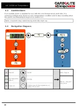
Solid-State Relay Replacement
Disconnect the product from the power supply and remove the
appropriate cover as given above.
1. Make a note of the wire connections to the solid state relay, then disconnect them.
2. Remove the solid state relay from the base panel or aluminium plate.
3. Replace and reconnect the solid state relay ensuring that the bottom of it has good
thermal contact with the base panel or aluminium plate.
4. Replace the access panel.
7.5
Thermocouple Replacement
Disconnect the product from the power supply. Remove terminal cover to
gain access to the thermocouple connections. Make a note of the
thermocouple connections.
Thermocouple cable colour codings are:
Thermocouple leg
Colour
positive (type K)
green
negative
white
Disconnect the thermocouple from its terminal block and withdraw the thermocouple
from its sheath by bending the metal tag or releasing the screw to release. It is also
advisable to remove the sheath and shake out any broken pieces of thermocouple.
Re-assemble with a new thermocouple, observing the colour coding, ensuring that the
thermocouple is not twisted as it is being inserted and that the metal tag is bent back to
grip the sheath.
Refit the element access panel.
7.6
Panel Element Replacement
See section 7.2 - wearing a face mask is required.
The chambers have two side-mounted refractory panels in which coiled heating
elements are inserted, normally out of sight behind silicon carbide chamber walls.
Disconnect the product from the electrical supply and remove the products back panel.
Make a written plan showing ALL the element and thermocouple connections. It is
important to make this plan for each individual product.
Disconnect all the element wire tails and thermocouple cables from their terminal
blocks.
Straighten all the element tails. Note that these become brittle with use.
37
7.0 Repairs and Replacements

