OperatiOn Manual
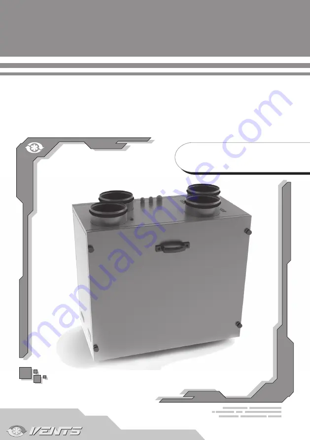
Vut 300 e2V eC
air supply and exhaust unit
with heat recovery
Страница 1: ...Operation Manual VUT 300 E2V EC Air supply and exhaust unit with heat recovery...
Страница 2: ...nd Operating Principle Installation and Setup Condensate Drainage Connection to power mains Unit control Technical Maintenance Fault Handling Storage and Transportation Regulations Manufacturer s Warr...
Страница 3: ...it is designed to arrange continuous air exchange by means of mechanical ventilation in private residences offices hotels cafes conference rooms as well as recuperation of heat energy contained in war...
Страница 4: ...r ducts IP 22 The unit series designations their main outside and connecting dimensions appearance and technical parameters are given on Figure 1 and in Table 1 The units undergo continuous improvemen...
Страница 5: ...5 Fig 1 Outside and Connecting Dimensions of the Unit 600 697 14 59 260 373 428 700 157 410 110 180 123 108 149 10 m cable...
Страница 6: ...Insulation 20 mm mineral wool Filter Air Exhaust Air Supply bag filter G4 Connected Air Duct Diameter mm 150 Weight kg 38 Recuperating Efficiency up to 85 Heat Exchanger Type Counterflow Heat Exchang...
Страница 7: ...nit design and operating logic are shown in Fig 2 The basic configuration includes 1 Exhaust fan 2 Supply Fan 3 Counter flow heat exchanger 4 Exhaust air filter class G4 5 Supply air filter class G4 6...
Страница 8: ...perating properly To enable proper post heating of the supply air install the duct temperature sensor in the air duct item 11 on Fig 2 at the minimum distance of 1 m from the supply air spigot The sup...
Страница 9: ...e access holes in the bottom of the wall mounted control panel Fig 4 Remove the back cover Disconnect the panel from the terminal block Lay the cable in the wall to the panel installation site Secure...
Страница 10: ...in delivery package and the sewage collection system with metal or rubber pipes Fig 6 The pipe pitch must be at least 3 Fill up the system with water before connecting the unit to the power mains Duri...
Страница 11: ...switch must ensure free access for quick power off of the fan The power conductor section is 2 5 mm2 The unit enables the following external connection options X3 terminal block markings as shown on...
Страница 12: ...Remote Control Remote Controller Unit On Off Fan Speed Up On Heater Off button Fan Speed Down Speed 1 Speed 3 Speed 2 Scheduled Operation On On Off Timer Wall Mounted Control Panel The unit is contro...
Страница 13: ...increase the speed or press the button to reduce the speed cyclically i e speed 1 speed 2 speed 3 From the remote controller Press the button to increase the speed or press the button to reduce the s...
Страница 14: ...ct upstream of the heat exchanger above the threshold value the unit slows the fans one increment down ATTENTION Upon deactivation with a working heater the unit continues operation for an additional...
Страница 15: ...he fan speed setup mode and press the and buttons simultaneously and hold them for 3 seconds Factory fan speed settings Speed 1 40 Speed 2 70 Speed 3 100 Fig 13 Fan Power Adjustment DuctTemperature Se...
Страница 16: ...wer mains Replace the filter see the sequence given in the Technical Maintenance section page 19 Switch on the unit by pressing the button on the wall mounted panel or the button on the remote control...
Страница 17: ...mounted control panel and then press the button Fig 17 Scheduled Operation Setup Mode Indicators Day Time Entry Number Heater Status Fan Speed Heater Off Heater On To select the scheduled operation se...
Страница 18: ...Off 12 00 2 speed Off 17 00 2 speed Off 23 00 1 speed Off Table 3 Sample programming sequence 9 Alarms In case of an emergency the unit switches off while the alarms are displayed on the wall mounted...
Страница 19: ...et accumulated inside the fans and reduce the unit performance and supply air flow Clean the fans with a soft brush or cloth No water and abrasive detergent sharp objects or solvents are allowed for c...
Страница 20: ...20 VUT 300 E2V EC Fig 19 Heat exchanger ad fitler maintenance 1 2 4 3...
Страница 21: ...21 Fig 20 Control unit maintenance 1 2 4 3...
Страница 22: ...ng the unit back on Low air flow Filter fan or heat exchanger clogging Clean or replace the filters Clean the fans and the heat exchanger Air handling system clogged or damaged Check for unobstructed...
Страница 23: ...TING FROM THE MANUAL REQUIREMENTS VIOLENCE THE UNIT MISUSE OR GROSS MECHANICAL EFFECT FULFIL THE REQUIREMENTS SET IN THE USER S MANUAL TO ENSURE PROPER FUNCTIONING OF THE UNIT AND LONG SERVICE LIFE Ma...
Страница 24: ...nce inspector Date of production _______________________________ Sold by Name of the trade company stamp of the shop____________________________________________ _______________________________________...
Страница 25: ...2012 V79ENG 02...