


11
www.ventilation-system.com
CONNECTION TO POWER MAINS
POWER OFF THE POWER SUPPLY PRIOR TO ANY OPERATIONS WITH THE UNIT.
THE UNIT MUST BE CONNECTED TO POWER SUPPLY BY A QUALIFIED ELECTRICIAN.
THE RATED ELECTRICAL PARAMETERS OF THE UNIT ARE GIVEN ON THE
MANUFACTURER’S LABEL.
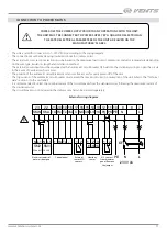
• The unit is rated for connection to 1~230 V/50 Hz according to the wiring diagram.
• The connection must be made using insulated conductors (cables, wires).
• The actual wire cross section selection must be based on the maximum load current, maximum conductor temperature depending
on the wire type, insulation, length and installation method.
• The external power input must be equipped with an automatic circuit breaker QF built into the stationary wiring to open the circuit
in the event of overload or short-circuit.
• The position of the automatic circuit breaker must ensure free access for quick power-off of the unit.
• The trip current of the automatic circuit breaker must exceed the maximum current consumption of the unit (refer to the “Technical
data” section or to the unit label).
• It is recommended to select the nominal current of the circuit breaker from the standard series, following the maximum current of
the connected unit.
• The circuit breaker is not included in the delivery set and can be ordered separately.
7
8
9
10
11
12
13
14
15
16
17
18
19
20
21
22
23
L
N
PE
PK
PK
+U
0-10V
GND
NO
C
GND
Tx
Rx
+U
SM-L
SM-N
L
N
QF
230 V AC
РЕ
2
1
2
1
3
+U
2
GND
1
0-10V
-
Tx
Rx
+
L1
N
SM1
L1
N
SM2
L
N
QF
230 V AC
РЕ
SM1
SM2
EXHAUST
External wiring diagram
SUPPLY
Electric actuators of
outer air dampers
Control panel
External
sensor N.O.
contact
Humidity
sensor
N.C. contact
from fire alarm
panel. Remove
the jumper
Содержание VUE 100 P3B EC
Страница 16: ...V146EN 04 ...


