SERVICE
Service - 50
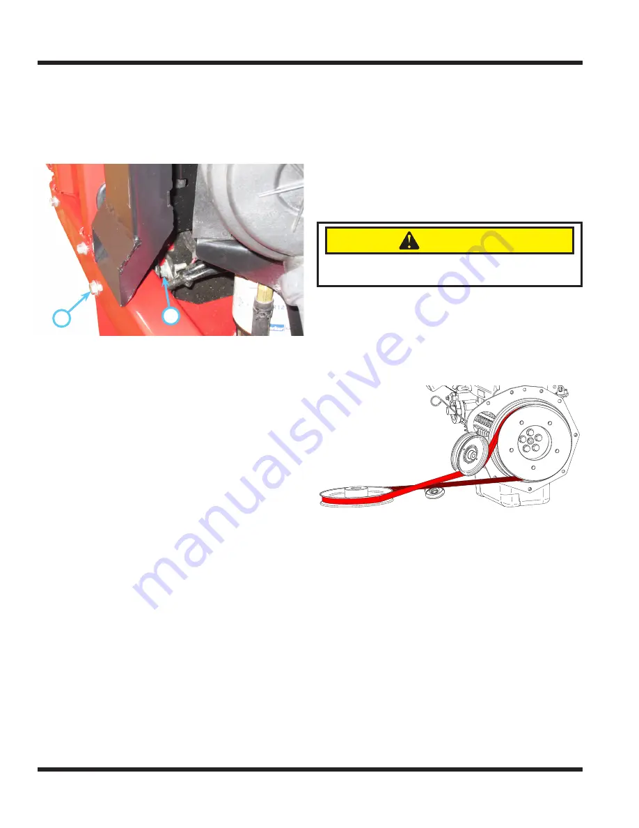
10. Loosen the locking nut (C) on the adjustment
bolt (D) at the left rear corner of the rear frame
and turn the adjustment bolt clockwise to move
the engine frame toward the rear of the main
frame or turn the adjustment bolt counterclock-
wise to move the engine frame toward the front
of the main frame.
11.
C
D
Once the engine frame has been properly
adjusted to achieve the correct drive belt align-
ment, torque the 4) bolts that fasten the engine
frame to the rear main frame to 31 ft-lbs (42 Nm).
12. Tighten the locking nut on the engine frame
adjustment bolt.
13. Install the top center pivot shield.
14. Install both center pivot canvas pieces.
Engine Drive Belt Replacement
1. Park the power unit on a level surface.
2.
Engage the parking brake and shut off the engine.
3. Remove the key from the ignition switch and
allow the engine to cool.
4. Open the left hood panel and remove the top
hood panel to access the engine compartment.
5. Remove both center pivot canvas pieces.
6. Remove the top center pivot shield.
7. Remove the engine drive belt cover.
8.
CAUTION
Spring may be under high tension. Use caution
when removing belt, to prevent pinching fingers.
Insert a 1/2” drive ratchet into the square cutout
in the end of the idler arm and rotate the idler
arm to release tension on the drive belt.
9. Remove the engine drive belt from the engine,
idler, and center shaft pulleys.
10. Install the new drive belt as shown and engage
the drive belt spring tensioner.
11. Check to ensure the belt is properly seated in
the pulleys.
12. When installing a new drive belt, verify the belt
alignment as directed in the Engine Drive Belt
Inspection & Adjustment section of the manual.
13. Install the engine drive belt cover.
14. Install the top center pivot shield.
15. Install both center pivot canvas pieces.
16. Replace the top hood panel and close the left
hood panel.
PTO Belt Replacement
1. Park the power unit on a level surface.
2.
Engage the parking brake and shut off the engine.
3. Remove the key from the ignition switch and
allow the engine to cool.
4. Remove both center pivot canvas pieces.
5. Remove the left and right center pivot guards.


