34
110332-02 - 6/22
PHTM II
Installation, Operating & Service Instructions
General System Piping Precautions
WARNING
Asphyxiation Hazard.
•
Failure to properly pipe boiler could cause
improper operation and damage to boiler or
building resulting in severe personal injury,
death or substantial property damage.
• Protect gas ignition system components from
water (dripping, spraying, rain, etc.) during
boiler operation and service (circulator
replacement, condensate trap cleaning, control
replacement etc).
• Oxygen contamination of boiler water will cause
corrosion of iron and steel boiler components
and could lead to premature boiler failure.
Warranty does not cover problems caused by
oxygen contamination of boiler water or scale
(lime) build-up caused by frequent addition of
water.
• Maintain clearances to system piping per
Figure 5-1.
Standard Piping Components
1. Safety relief valve (required).
A. Shipped loose in parts carton (30 psig [207
kPa]).
CAUTION
Toxic Material.
The heat transfer medium must be water or
other nontoxic fluid having a toxicity rating or
Class of 1, as listed in
Clinical Toxicology of
Commercial Products
, 5th edition.
10
Heating System Piping
!
!
2. Pump (required)
Boiler loop pump is supplied with this boiler and
sized for near boiler piping equivalent length of 50
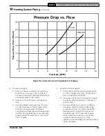
ft. See Table 10-1 for flow range through boiler. At
least one additional pump is required on system
side.
B. Pipe outlet of safety relief valve to location
where water or steam will not create a
hazard or cause property damage if valve
opens. (The end of discharge pipe must
terminate in unthreaded pipe.)
C. If safety relief valve discharge is not piped to
drain, it must terminate within 6 in. (150 mm)
of floor.
D. Do not route discharge piping through an
area that is prone to freezing temperature.
E. Termination of safety relief valve must be in an
area where it is not likely to become plugged
by debris.
F. If replaced, replacement must have a setting
less than or equal to maximum allowable
working pressure (MAWP) shown on ASME
data plate located on left side of heat
exchanger (50 psig [345 kPa]).
Boiler Model
Boiler Supply
Connection
inch, FPT
Boiler Return
Connection
inch, FPT
ΔT = 35°F
ΔT = 30°F
ΔT = 25°F
ΔT = 20°F
Minimum
Required
Flow
(GPM)
Boiler
Head
Loss,
(ft.)
Minimum
Required
Flow
(GPM)
Boiler
Head
Loss,
(ft.)
Minimum
Required
Flow (GPM)
Boiler
Head
Loss,
(ft.)
Minimum
Required
Flow
(GPM)
Boiler
Head
Loss,
(ft.)
PHTM2180H
1
1
6.4
11.2
7.5
14.6
9.0
20.0
11.2
29.7
PHTM2150H
1
1
8.1
8.2
9.4
10.9
11.3
15.3
14.1
23.4
PHTM2180H
1
1
9.7
11.6
11.3
15.5
13.5
21.8
16.9
33.5
Notes:
1. Required Flow (GPM) = **Output (MBH) x 1000/(500 x ΔT)
**Output (MBH) - select value for specific boiler model from Table 3-1. Using boiler antifreeze will result in higher pressure drop
and may require larger circulators.
2. Boiler head loss includes 50 eq. ft. near boiler piping. [Approximately 20 ft. straight pipe, (4) 90° elbows and (2) full port ball
valves]
Table 10-1: Head Loss at Selected Flow Rates
WARNING
Burn Hazard.
Safety relief valve discharge piping must
be piped near floor to eliminate potential
of severe burns. Do not pipe in any shut-off
valves between:
1. Safety relief valve and boiler.
2. Safety relief valve and discharge.
Union may be installed in safety relief valve
piping.
!

