1
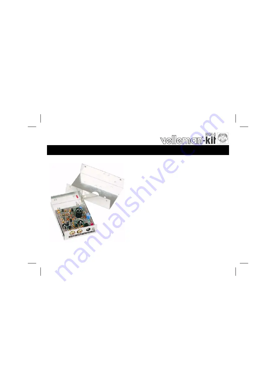
AUDIO / VIDEO MODULATOR
K4601
ILLUSTRATED ASSEMBLY MANUAL
H4601IP-2
Total solder points: 131 Difficulty level:
beginner
2
3
4
5
advanced
Conver
t an au
dio and
video s
ignal in
to a
UHF TV
signal.
Страница 1: ...1 AUDIO VIDEO MODULATOR K4601 ILLUSTRATED ASSEMBLY MANUAL H4601IP 2 Total solder points 131 Difficulty level beginner 1 2 3 4 5 advanced Convert an audio and video signal into a UHF TV signal...
Страница 2: ...2...
Страница 3: ...ational telecommunications authority it is permitted to use this modulator as a mini transmitter by connecting a small antenna to it With this facility it is possible to receive the signal from the vi...
Страница 4: ...he eyes Needle nose pliers for bending leads or to hold components in place Small blade and Phillips screwdrivers A basic range is fine For some projects a basic multi meter is required or might be ha...
Страница 5: ...nts are cone shaped and shiny 3 Trim excess leads as close as possible to the solder joint REMOVE THEM FROM THE TAPE ONE AT A TIME AXIAL COMPONENTS ARE TAPED IN THE CORRECT MOUNTING SEQUENCE You will...
Страница 6: ...B R13 2K7 2 7 2 B R14 5K6 5 6 2 B R15 270K 2 7 4 B 3 1 4W Resistors R Construction ZD1 11V ZD2 6V2 1 Zener diodes Watch the polarity ZD1 CATHODE C1 3pF 3 3 C2 3pF 3 3 C3 3pF 3 3 C4 1pF 1 red C5 3pF 3...
Страница 7: ...to the exact length Scrape the enamel off the ends of each length of wire with a sharp knife for about 5 mm and tin the ends Make up the windings on a gimlet of 3 5mm diameter L1 3 turns Cu 0 6mm Fig...
Страница 8: ...dio J2 Video 12 RCA connectors J C20 4 7 C21 4 7 C22 10 F C23 10 F C24 220 F 13 Electrolytic Capacitors Watch the polarity C L4 10 7MHz 14 High frequency transformer J3 RF 15 Antenna connector LD1 Red...
Страница 9: ...ion Insert the red LED into the housing as in the drawing Pay attention to the polarity Now connect the two wires with the pins of the LED respect the polarity Cathode Anode Solder them together Fig 6...
Страница 10: ...truction Attach the sticker giving the connection information to the back of the housing Mount the 3 threaded rods on the bottom of the housing together with a tooth lock washer and M3 countersunk hea...
Страница 11: ...ble and connectors connect the antenna output of the modulator to the antenna input of the TV set or connect a 30cm length of stiff wire to the modulator antenna connector ATTENTION As soon as an ante...
Страница 12: ...capacitor to a different setting turn 1 to 2 mm per test Expand or compress see fig 9 0 also have an influence on the picture quality and it is always necessary to close the housing before doing the...
Страница 13: ...variations in inductor L2 and potentiometer RV2 can greatly improve the picture quality Setting the sound Once a good picture has been obtained the sound carrier can be set Carefully turn the core of...
Страница 14: ...C17 C23 ZD1 C3 R10 L3 RF C4 GND C5 R6 T4 C9 C7 C14 RV2 C6 R13 LD1 C2 R7 C16 VCC T2 L1 C1 CV1 VCC ZD2 R8 C18 R12 R5 R11 C8 C10 C15 C12 T1 R9 C13 C20 RV1 R2 C22 C19 GND GND IN IN R15 C21 C11 T3 L4 R3 L2...
Страница 15: ...15 21 PCB PCB...
Страница 16: ...ations and typographical errors reserved Velleman Components nv H4601IP 2004 ED2 VELLEMAN Components NV Legen Heirweg 33 9890 Gavere Belgium Europe www velleman be www velleman kit com 5 4 1 0 3 2 9 2...