background image

1.  General description

The 

ekor

.rtk unit is electronic equipment developed to 

indicate the absence of voltage on medium-voltage (MV) 

lines. It is for use in local or remote control installations 

where information on the status of the lines is required.

The unit is built into the switchgear and uses the same 

capacitive current signal as the 

ekor

.vpis voltage 

presence indicators to perform detection functions. Thus, 

conventional medium-voltage line coupling systems such 

as voltage transformers are not required, as it takes this 

signal directly from the capacitor dividers installed in the 

bushings.

The 

ekor

.rtk unit is supplied duly installed, configured 

and factory-tested, fitted in the circuit-breaker and feeder 

functions of 

cgmcosmos

 and 

cgm

.3 system cubicles.

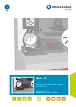
Figure 1.1.  ekor

.rtk

 unit with support for 

cgmcosmos

-l 

cubicles

a

ekor

.rtk

Figure 1.2.  ekor

.rtk

 unit with support for 

cgmcosmos

-l 

cubicle

IG-094-EN version 09; 01/08/2019

4

General description 


General instructions

ekor

.rtk: Setting and assembly  

of the voltage detection unit

Содержание ORMAZABAL ekor.rtk

Страница 1: ...LIB ekor rtk Setting and assembly of the voltage detection unit General instructions IG 094 EN version 09 01 08 2019...

Страница 2: ...ectrical installations Personnel must be fully familiar with the instructions and warnings contained in this manual and in other recommendations of a more general nature which are applicable to the si...

Страница 3: ...um L1 L2 L3 8 3 Technical specifications 9 3 1 Rated values 9 3 2 Mechanical design 9 3 3 Insulation tests 9 3 4 Electromagnetic compatibility 10 3 5 Climatic tests 10 3 6 Mechanical tests 10 4 Voltag...

Страница 4: ...entional medium voltage line coupling systems such as voltage transformers are not required as it takes this signal directly from the capacitor dividers installed in the bushings The ekor rtk unit is...

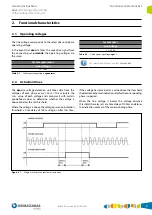
Страница 5: ...This calculate the r m s value of each voltage and compares it with certain pre defined values to determine whether the voltage is above or below the set threshold Where the voltage is above the volt...

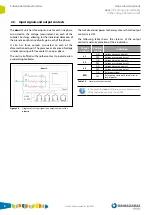
Страница 6: ...ekor rtk The lack of external power to the relay means that all output contacts are OFF The following table shows the statuses of the output contacts and an explanation of their indication Output con...

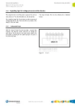
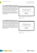
Страница 7: ...2 4 1 Independent Logic With this type of logic the unit provides a contact that indicates the absence and or presence of voltage for each phase The terminals to be accessed to obtain the information...

Страница 8: ...als J1 6 J1 7 Figure 2 4 Terminals 2 4 3 Voltage absence OR Logic Sum L1 L2 L3 With OR logic the unit terminal block provides the information on the absence of voltage in the event of a lack of voltag...

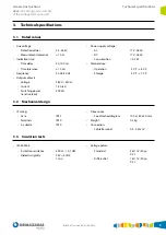
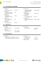
Страница 9: ...Temperature Operation 40 C 60 C Storage 40 C 70 C 3 2 Mechanical design IP rating Case IP47 Terminals IP2X In cubicle IP3X Dimensions See attached diagram 100 x 180 x 40 mm Weight 0 3 kg Connection Ca...

Страница 10: ...00 4 12 Sinusoidal damped wave 2 kV 1 kV EN 50081 2 55011 Radiated emissions Group 1 150 kHz 30 MHz Class A 3 5 Climatic tests IEC 60068 2 1 Slow changes Cold 40 C 960 min IEC 60068 2 2 Slow changes H...

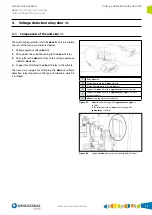
Страница 11: ...on the type of cubicle in which it is installed 1 Relay ekor rtk 2 Wiring from bushing to ekor rtk relay 3 Wiring from ekor rtk relay to ekor vpis 4 Support for ekor rtk relay in cgmcosmos l feeder cu...

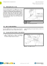
Страница 12: ...ting status 1 Test push button 2 Indication LED Figure 4 3 Test push button and indication LED 4 3 ekor rtk relay installation To install an ekor rtk relay in a cubicle you must have the ekor rtk volt...

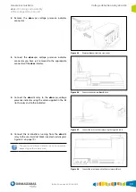
Страница 13: ...the cable supplied in the kit to the relay and to the indicator Figure 4 7 Connect the relay to the display using the supplied cable 5 Connect the terminations running from the ekor rtk relay to the...

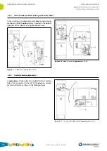
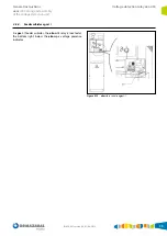
Страница 14: ...Figure 4 10 ekor rtk in cubicles cgmcosmos v R AV 4 3 3 Feeder cubicles cgmcosmos l In cgmcosmos l feeder cubicles the ekor rtk relay is located below the manometer to the left of the ekor vpis voltag...

Страница 15: ...lay is located at the bottom right below the ekor vpis voltage presence indicator Figure 4 12 ekor rtk in cubicles cgm 3 l IG 094 EN version 09 01 08 2019 15 General instructions ekor rtk Setting and...

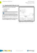
Страница 16: ...SW3 defines the actuation time and SW4 specifies the line frequency The possible configurations obtained using selector S1 are those shown below depending on the system to which the cubicle where the...

Страница 17: ...50 Hz ON X cgmcosmos system cubicles with voltage presence indication from the ormalink connecting set SW1 SW2 Voltage SW3 Time SW4 Frequency OFF X X 3 5 36 kV 100 ms X 50 Hz ON X cgm 3 system cubicl...

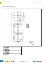
Страница 18: ...icator ekor vpis E Output contacts F Power supply G Test push button W0 Error output Figure 5 1 Connection diagram of relay ekor rtk IG 094 EN version 09 01 08 2019 18 Connection diagram General instr...

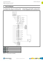
Страница 19: ...s cgm 3 and diagram 996414 for cubicles cgmcosmos which are included with the unit A Power supply S l1 L1 output S l2 L2 output S l3 L3 output B Bushing cgm W0 Error output Figure 6 1 Connection diagr...

Страница 20: ...7 Dimensions Figure 7 1 Dimensions in mm for relay ekor rtk IG 094 EN version 09 01 08 2019 20 Dimensions General instructions ekor rtk Setting and assembly of the voltage detection unit...

Страница 21: ...General instructions ekor rtk Setting and assembly of the voltage detection unit Notes Notes IG 094 EN version 09 01 08 2019 21...

Страница 22: ...Notes General instructions ekor rtk Setting and assembly of the voltage detection unit Notes IG 094 EN version 09 01 08 2019 22...

Страница 23: ......
Страница 24: ...Subject to change without prior notice For further infotmation contact Ormazabal www ormazabal com Ormazabal Protection Automation IGORRE Spain...

Отзывы: