6. Electrical diagram
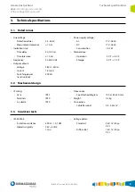
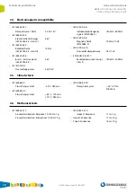
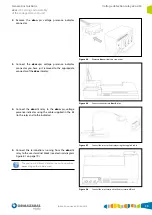
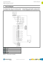
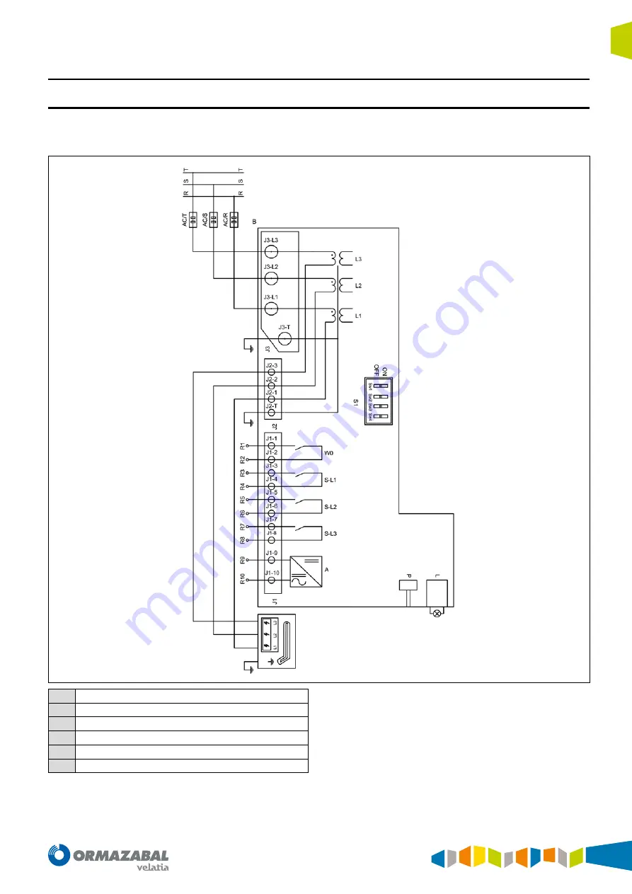
The following figure shows the electrical diagram
corresponding to the relay
ekor
.rtk. For greater detail, see
diagram 996235 for cubicles
cgm
.3, and diagram 996414,
for cubicles
cgmcosmos
, which are included with the unit.
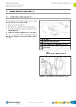
A
Power supply
S
-l
1
L1 output
S
-l
2
L2 output
S
-l
3
L3 output
B
Bushing
cgm
W0
Error output
Figure 6.1.
Connection diagram of relay
ekor
.rtk
IG-094-EN version 09; 01/08/2019
19
General instructions
ekor
.rtk: Setting and assembly
of the voltage detection unit
Electrical diagram
Содержание ORMAZABAL ekor.rtk
Страница 23: ......

