background image


Vega TL-11 / User Manual 


10 

Revision 03 - 07 September 2020


INDICATION 

The device has one red LED located on the board. Indication is only used during device 

activation step in the LoRaWAN network and when operation modes are switch.  


LED signal 

Meaning 


Series of short flashes 

Connection to the network is proceed 


One long flash 

The device connected to the network 
and is in active mode 


Three long flashes 
 

Linking to the network is unsuccessful 
or the device switched to the «Storage» 
mode 


In case of connection attempt fail, the device will continue to 
accumulate data and will attempt to connect to the network every 6 
hours 

LED location on 

the board 

Содержание TL-11

Страница 1: ...www vega absolute ru TEMPERATURE LOGGER VEGA TL 11 User Manual...

Страница 2: ...from Russian Document number V02 TL11 01 Revision and date 03 07 September 2020 This document applies to the following products Product name Type number End devices Vega TL 11 Revision History Revisio...

Страница 3: ...ndication 10 Initial startup 11 Connecting via USB 12 4 VEGA LORAWAN CONFIGURATOR 14 Interface of the application 14 Connection to the device 15 Device info tab 16 LoRaWAN settings tab 18 Vega TL 11 T...

Страница 4: ...To provide the stable radio between the gateway and the end device it is recommend avoiding the device installation in the places which are barriers for the radio signal getting through like a reinfor...

Страница 5: ...AND DATA COLLECTION ALGORITHM The readings collecting from the thermistor with a configurable period from 5 minutes to 24 hours The readings stored in the device memory and transmitting during the ne...

Страница 6: ...nd Storage mode o ADR support Adaptive Data Rate o Sending of confirmed packets configurable o Extra communication in case of tamper sensor actuation MARKING Device marked with sticker that contain th...

Страница 7: ...based Activation type ABP or OTAA Communication period 5 15 30 minutes 1 6 12 or 24 hours Data collection period 5 15 30 minutes 1 6 12 or 24 hours Memory amount for storing packets 1300 packets Ante...

Страница 8: ...ct pairs One pair Therm1 and contacts is for connect to built in thermistor another one is for external probe Therm2 and contacts You should configure sending data parameters in Vega LoRaWAN Configura...

Страница 9: ...ga TL 11 User Manual 9 Revision 03 07 September 2020 DEVICE SENSORS Tamper is located on the board top Should the tamper triggering the device sends a corresponding message to the LoRaWAN network Tamp...

Страница 10: ...witch LED signal Meaning Series of short flashes Connection to the network is proceed One long flash The device connected to the network and is in active mode Three long flashes Linking to the network...

Страница 11: ...lication See part 4 1 ABP After pressing the start button the device immediately starts working in the Active mode 2 OTAA After pressing the start button the device makes three attempts to connect to...

Страница 12: ...nfigurator application See part 4 Before connecting the device to the computer for the first time you must install the driver for the COM port stsw stm32102 which can be downloaded from iotvega com Af...

Страница 13: ...is window you need to click Next then Install and then the installation will begin When the installation is completed successfully the following screen appears After pressing Finish the driver is read...

Страница 14: ...sic settings advanced settings and the ability to check the coverage area of the signal from the gateways are available Next the work of the application is considered in the Expert mode INTERFACE OF T...

Страница 15: ...vice perform the following steps 1 Connect the USB cable to the device 2 Start the Vega LoRaWAN Configurator application 3 Click the Connect button in the menu on the left The application automaticall...

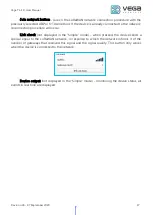
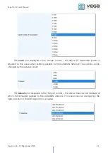
Страница 16: ...d Over The Air Activation is displayed Regional info not displayed in the Simple mode shows the frequencies of the JOIN channels and the second receiving window These frequencies can be changed in the...

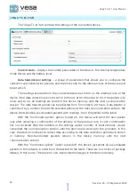
Страница 17: ...procedure will occur Link check not displayed in the Simple mode when pressed the device sends a special signal to the LoRaWAN network in response to which the network informs it of the number of gate...

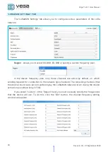
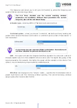
Страница 18: ...ency plan only those channels are active by default on which sending requests for connection to the network join channels The remaining channels that the device should use can be transferring by the L...

Страница 19: ...nfirmation or until the Uplink number of transmission is over see below If you choose to send a packet without confirmation the modem will not know whether the packet is delivered or not ADR this opti...

Страница 20: ...etwork while OTAA mode active The second window always opens after 1 second after the first Uplink number of transmission not displayed in the Simple mode if the Confirmed uplinks function is disabled...

Страница 21: ...adjusted to this value when sending packets to the LoRaWAN network This option can be changed by the network server TX datarate not displayed in the Simple mode the device transmission datarate at wh...

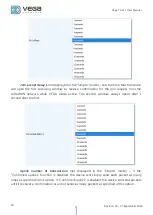
Страница 22: ...ta transfer is carried out by a random time at the selected period At the next communication session the device starts sending accumulated packets with readings from the earliest to the latest With th...

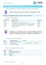
Страница 23: ...hermistor in C multiplied by 10 int16_t 1 byte Temperature of external probe in C multiplied by 10 int16_t 1 byte Main parameters uint8_t If thermistor is not connected to the TL 11 in the Temperature...

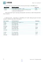
Страница 24: ...package the application can send to modem the packet with time correction 3 Settings packet transmitting on LoRaWAN port 3 when settings request command received or device connected to the network Si...

Страница 25: ...tion Data type 1 byte Packet type this packet 1 uint8 Answering that packet the device sends the packet with settings 3 Packet with settings is identical to such packet from device Size in bytes Field...

Страница 26: ...byte 1 confirmed 2 unconfirmed 5 Adaptive data rate 1 byte 1 on 2 off 8 Uplinks number of transmission 1 byte from 1 to 15 16 Communication period 1 byte 1 1 hour 2 6 hours 3 12 hours 4 24 hours 5 5 m...

Страница 27: ...NSPORTATION REQUIREMENTS Vega TL 11 shall be stored in the original packaging in heated room at temperatures 5 to 40 and relative humidity less than 85 The device shall be transported in covered freig...

Страница 28: ...Vega TL 11 User Manual 28 Revision 03 07 September 2020 7 CONTENT OF THE PACKAGE Vega TL 11 device is delivered complete with Temperature logger Vega TL 11 1 pc Factory certificate 1 pc...

Страница 29: ...specified in this user manual Warranty does not apply to power supplies of devices sending more than 80 000 packets the device with mechanical electrical and or other damages and defects caused by vio...

Страница 30: ...Vega TL 11 User Manual 30 Revision 03 07 September 2020 vega absolute ru Operation Manual Vega Absolute OOO 2019 2020...

Отзывы: