Troubleshooting
Display Is Dark After Boot-Up Sequence
16
Table 8. Troubleshooting Procedure For Dark Display
Probable Cause
Action
OK?
Action
1. One end of the
Display ribbon
cable is loose or
out of its con
-
nectors.
1. Remove the console’s cover and the Display/CPU assembly following the assem
-
bly removal steps beginning on page 26.
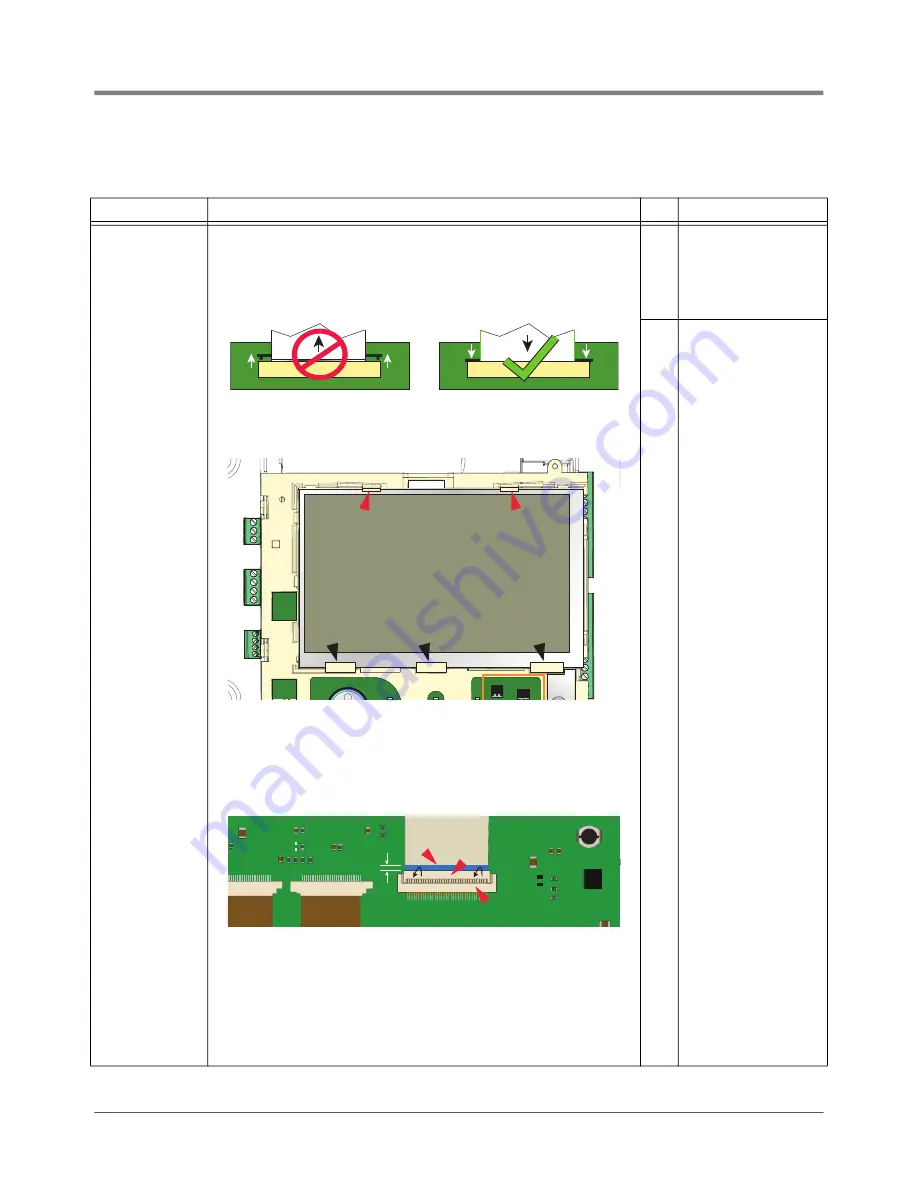
2. Verify the Display ribbon cable (Item 4 in Figure 3) is securely seated in its CPU
board connector and that both sides of the locking latch are down against the con
-
nector as shown below:
3. Place the Display/CPU Assembly on a clean surface, Display side up.
4. Place your thumbs against the spring tabs at the top of the display indicated by
the upper (red) pointers in Figure 13, and gently push them away from the top of
the display as you can tilt the top of the display up enough to clear the tabs.
5. Slide the display up and out from under the three angular base supports indicated
by the lower (black) pointers.
6. Holding the Display/CPU Assembly in one hand carefully rotate the display away
from the Display/CPU Assembly until the cable connector on the back of the dis
-
play can be seen. The cable is not very long and can pull out if the display is
rotated too far from the Display/CPU Assembly.
7. If inserted fully, the blue end of the cable (1 pointer) will a maximum of 1/16”
(2mm) above the connector on the back of the display as shown below:
8. If the cable appears loose or out of the display connector, remove the Display
cable from its CPU connector, reversing the procedure in Step 2 above.
9. Place the Display face down on a clean surface and rotate the locking member of
the cable’s Display connector (2 pointer) up 90° from the connector’s fixed base (3
pointer). Reseat the cable end into the display board connector as far as it will go
and then push the locking member down onto the connector snapping it in place.
10.Replace the Display board into its place in the Display/CPU Assembly reversing
the steps above.
11.Reseat the CPU board end of the Display cable as discussed in step 2 above.
No
Insert ribbon cable fully
into its CPU board connec
-
tor and push down on each
side of the locking latch
until it rests against the
connector.
Yes
Replace Display/CPU
assembly.
P2 RS485
J39
J38
P2 RS232
P1 RS232
+
1/16” (2mm)
1
2
3
Содержание TLS4/8601 Series
Страница 1: ...Manual No 577014 058 Revision C Troubleshooting Manual TLS4 8601 Series Consoles...
Страница 43: ......


