Troubleshooting
Replacing the Power Supply Board
53
Replacing the Power Supply Board
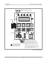
The Power Supply board must be replaced when:
•
Probe data is not being processed, or
•
The voltage between the GND and 8V test points [Figure 19] on the back of the CPU board is less than 7 Vdc.
1. Turn Off power to the system.
2. Disconnect the CPU cable from the Power Supply board.
3. Tag and disconnect probe and power.
4. The Power Supply board is secured by two T-15 Torx screws in the top of the board. You must also remove the two
screw locks which go through the bottom of the console into the DB-9 connector before you can lift out the board.
After removing the Torx screws (and screw locks), slowly lift up on the board until the lower tabs on the board clear
the slots in the bottom of the console, then continue to lift the board out.
5. Replace the board by reversing the above steps.
6. Turn on power to the system. The system will perform a warm boot procedure [page 21] and the display will return to
the top level status screen. You do not have to reprogram the console after replacing the Power Supply board.
Display Messages
TANK PARAMETERS
The following tank parameters are displayed one at a time as the operator scrolls through the Top Level Menu.
•
Product Height,
•
Product Temperature (requires probes that have temperature measurement capability),
•
Water Height (requires probes that have water measurement capability).
Pressing the Tank key allows the user to select which tank's data is displayed. If a parameter is not available for any tank
in the system, that display will not appear as you scroll through the menus. When viewing a display that is available in
one of the tanks, but is not available for the current tank, a “
NO DATA
” message will be displayed for that parameter.
Alarms
When an alarm occurs, the console’s internal beeper will activate (if enabled), the front panel LED will flash red, and the
top line of the display will contain the alarm message. In the case of multiple alarms, the main display screen will
automatically scroll through the active alarms. Press the Silent key to switch Off the internal beeper and acknowledge the
alarm. The red LED will continue to flash until the alarm condition is remedied.
When an alarm condition returns to the normal state the alarm will be removed from the list of alarms. If no alarms are
active, the LED will return to the Normal state (continuous green), the beeper will be switched Off, and the top line of
the display status line will read ALL FUNCTIONS NORMAL.
Displayed Alarm Messages
•
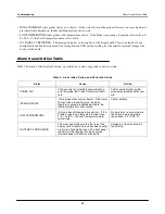
PROBE OUT (all probes) - If the console is not reliably communicating with the probe, the Probe Out alarm will
activate.
OFF


