background image

Module Removal/Installation

Installing A Comm Module

11

Installing A Comm Module

Disconnect, tag and lockout power to the TLS-450PLUS console be-
fore starting this procedure.

1. Referencing Figure 4, open the left and right doors of the console.

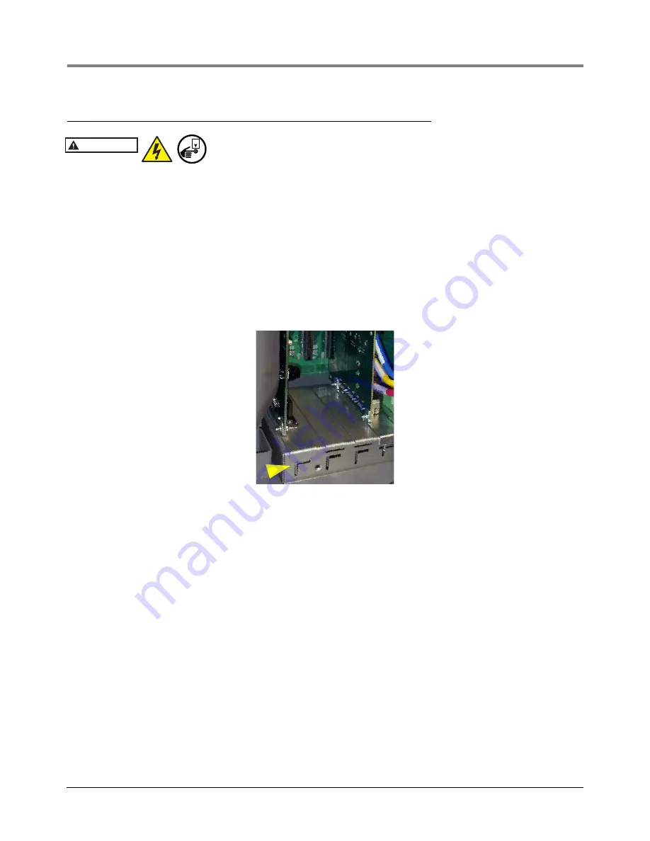
2. The Comm Bay is divided into 5 communication slots numbered from 1 to 5 going left to right (see Figure 3). 

Only slots 1-3 are available for user-selectable Comm modules (ref. Table 3). The Comm modules in Slots 4 
and 5 are fixed and cannot be moved. 

3. Using a T-15 Torx driver, loosen the module clamp securing screw and remove the clamp (see Figure 3).

4. Remove the blank cover from underneath the desired comm slot by punching it into the console or by using 

pliers to remove it from the inside of the console. Be careful not to damage any internal components in the 
process of removing the blank cover.

5. Place the new Comm module in the slot. Align the edge connector on the back of the board in the center of the 

vertical connector on the Comm Backplane board, then push the board firmly in as far as it can go. The sheet 
metal bracket of the Comm module slides into the slot and the front edge of the bracket fits into the keyed slot 
in the front of the Comm Bay.

Figure 6.   Comm Module Bracket Keyed Slot

6. After the Comm module(s) is installed, replace the comm module clamp and the screw that secures it.

7. Connect applicable interface cable(s) to the module(s) as defined in the POS Application Guide 577013-401. 

Record the slot/configurable port for each installed module which will be needed in the communication setup 
procedure.

8. Close the console’s front doors, reversing the procedure in Step 2 of “Removing An Interface Module” on 

page 7.

9. Power up the console and perform a DB Restore, then follow the communication setup procedure for the newly 

installed module(s) using the TLS-450PLUS Online help. 

WARNING

OFF

Содержание TLS-450PLUS

Страница 1: ...Manual No 577014 077 Revision D Module Replacement Instructions TLS 450PLUS Console...

Страница 2: ...ur Terms and Conditions VEEDER ROOT S PREFERRED CARRIER 1 Contact Veeder Root Customer Service at 800 873 3313 with the specific part numbers and quantities that were missing or received damaged 2 Fax...

Страница 3: ...0 Amp Controller Interface Module 10 Installing A Comm Module 11 Installing Software Features Software Features Installation Procedure 12 Figures Figure 1 USB Module USB ports 3 Figure 2 DB Backup Scr...

Страница 4: ...cation Guide 577014 110 TLS 450PLUS TLS4 Operator s Manual Table 1 Module Bay Modules Part No Item 332812 001 Universal 16 Sensor Probe Interface Module 332813 001 Universal Input Output Interface Mod...

Страница 5: ...nk Warranty Registrations may only be submitted by selected Distributors Safety Precautions The following safety symbols may be used throughout this manual to alert you to important safety hazards and...

Страница 6: ...ackup 1 Beneath the left side of the TLS 450PLUS console locate the USB module and insert the V R Backup thumb drive minimum 4 GB P N 332970 004 into one of the external USB ports P N 333477 001 see i...

Страница 7: ...ackup Destination field to select the Backup thumb drive inserted in Step 1 then follow the on screen instructions to backup TLS 450PLUS console data Figure 2 DB Backup Screen System Status 07 20 2013...

Страница 8: ...4 4 5 L1 G N L2 MODULE PERMISSIBLE SLOT S USM Module 1 2 3 or 4 USM Module w ATM Pressure Board 4 Only I O Module MDIM LVDIM 10 Amp Controller Port 2 Right door of console Comm module clamp securing s...

Страница 9: ...Table 3 User Selectable Comm Module Permissible Slots and Port Availability Comm Module Comm Type Slot 1 Slot 2 Slot 3 Port Port Port 1 2 1 2 1 2 RS 232 Single Port also EDIM Satellite S SAT and Sate...

Страница 10: ...e Interface Module by its 3 5 inch handle and pull it out of the slot 7 Once an Interface Module is removed it must be replaced with another Interface Module or blank cover P N 332580 001 in the openi...

Страница 11: ...3 illustrates acceptable non intrinsically safe module positions in the Interface Module Bay of the console 3 Remove the plug in wiring terminal block from the front of the Interface Module loosen the...

Страница 12: ...nectors that plug into slots 5 Place the USM Module on a clean surface Get the ATM Pressure Board P N 332665 001 6 Align the male connector and two support posts of the ATM Pressure board over the fem...

Страница 13: ...d tighten the screws 4 Write in the device name for each wire connection on the module s wiring label attached to the inside of the door Once all devices are connected plug the terminal block back int...

Страница 14: ...he blank cover 5 Place the new Comm module in the slot Align the edge connector on the back of the board in the center of the vertical connector on the Comm Backplane board then push the board firmly...

Страница 15: ...Button Into USB Adapter 2 Replace the plastic retaining cap on the adapter after inserting the i Button 3 Plug the USB Adapter into one of the two USB ports in the console s USB module see Figure 1 4...

Страница 16: ...For technical support sales or other assistance please visit www veeder com...

Отзывы: