


A-
1
Appendix A: EMR4 Safety Instructions & System Specifications
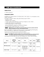
1. ATEX approved EMR4 systems are marked with the following information defining its limits for safe use.
•
This equipment must be installed according to the applicable installation document. For UL/cUL installations
use Control Drawing number 331940-021 and for ATEX installations use Descriptive System Document
number 331940-022. For IECEx installations use Descriptive System Document number 331940-022.
•
Defined per certification DEMKO 17 ATEX 1889X or IECEx UL 17.0054X.
2. Refer to the site preparation procedures in this manual for general instructions on safe installation, use, and
replacement.
3. The EMR4 system does require periodic calibration. Follow the calibration procedures outlined in the Veeder-
Root EMR4 Setup and Operation manual (P/N 577014-350).
4. The EMR4 system is not serviceable. If a failure occurs, the unit should be replaced in accordance
with the requirements of this manual.
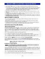
Special Conditions
F
or Safe Use
•
For ambient temperatures below -10°C and above +60°C use field wiring suitable for both minimum and
maximum ambient temperature.
•
All installations must be made in accordance with the accompanying Descriptive System Documentation.
•
The devices have not been evaluated for use across a boundary wall.
•
The display head, remote display head, thermoprobe, pulse encoder, corner switch and optional keypad all
contain aluminum. Care must be taken to avoid ignition hazards due to impact or friction.
General Overview Of The ATEX Directive
ASSOCIATED APPARATUS
The Veeder-Root EMR4 Interconnect Box (IB) is installed in an indoor, non hazardous area. The IB has barriers
that protect the linked apparatus by an
[Exia]
intrinsically safe mode of protection and are suitable to control
apparatus installed into areas that are likely to become hazardous in the presence of concentrations of gases,
vapours or mists formed by group
IIA
dangerous substances. The symbols on the nameplate have the following
meaning:
All ATEX models of the
EMR4 IB
are in compliance with Directive
2014/34/EU (ATEX)
.
A sample EMR4 IB has been evaluated and tested by
UL International Demko A/S
, Borupvang 5A, 2750
Ballerup, Denmark Tel.+45 44 85 65 65,
and approved by the issue of the EC type
certificates:
DEMKO 17 ATEX 1889X
or
IECEx UL 17.0054X
EMR4 Interconnect Box
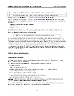
INTRINSICALLY SAFE APPARATUS
IT IS AN INTRINSICALLY SAFE APPARATUS WHEN IT IS INSTALLED FOLLOWING THE
MANUFACTURER’S INSTRUCTIONS IN THE MANUAL.
The Veeder-Root EMR4 Display Head is an intrinsically safe apparatus, marked
Ex ia
, suitable for installation into
areas that are likely to become hazardous in the presence of concentrations of gases, vapours or mists formed by
group
IIA
dangerous substances. The temperature class of the devices is
T4
(surfaces temperatures lower than
135°C). The symbols on the nameplate have the following meaning:
e
Device suitable to be installed in potentially explosive areas
II
Group II: for installations in areas other than mines and related surface equipment
(I)
Category 1: suitable to control apparatus installed into Zone 0, Zone 1 or Zone 2 hazardous areas
G
For potentially hazardous areas characterised by the presence of gases, vapours or mists
e
Device suitable to be installed in potentially explosive areas
II
Group II: for installations in areas other than mines and related surface equipment
NOTICE