background image

24

Operating Instructions

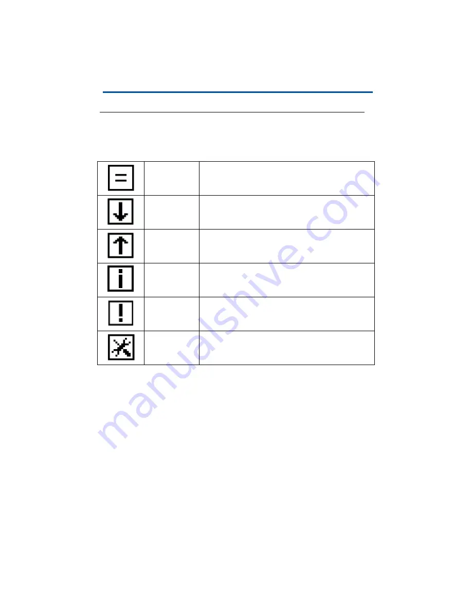
Display Icons

Display Icons

The following icons at the top left of the display are used to indicate the various 
states of the DIS-51.

Normal

No change in level (volume). The level for the displayed 
tank is not currently changing. This indicates not dis-
pensing and no delivery.

Dispensing

Dispensing is currently taking place out of the displayed 
tank. The level (volume) decreases.

Delivery

A delivery into the displayed tank is currently taking 
place. The level (volume) increases.

Information

The DIS-51 display is showing information data (e.g. site 
information).

Alarm and Error

There is an error preventing the normal display of data 
for a single tank or for all tanks.

Configuration

The DIS-51 is in configuration mode.

Содержание DIS-51

Страница 1: ...Manual No 577014 445 Revision C DIS 51 Installation Setup Operation Guide ...

Страница 2: ...ined in this publication may be subject to change without notice This publication contains proprietary information which is protected by copyright All rights reserved No part of this publication may be photocopied reproduced or translated to another language without the prior written consent of Veeder Root Example Illustrations Illustrations used in this publication may contain components that are...

Страница 3: ...Software Setup For Serial Port RS 485 On TLS 350R Option 1 10 OPTION 2 10 Wiring Diagram For Option 2 10 Software Setup For Serial Port RS 232 On TLS 350R Option 2 10 Connection Instructions DIS 51 to TLS4 11 RS 485 Serial Port Configuration On TLS4 11 Wiring Diagram 11 Software Setup For TLS4 Serial 2 Port 11 Connection Instructions DIS 51 to TLS 450 Series 13 RS 485 Serial Port Configuration On ...

Страница 4: ...igures Figure 1 System Block Diagram 4 Figure 2 DIS 51 Junction Box Wiring Diagram 6 Figure 3 Serial Comm Wiring Input Options 7 Figure 4 Serial Port Configuration For TLS2P 8 Figure 5 Single Port RS 485 Module For TLS 350R DCD Configuration 9 Figure 6 Serial Port 2 J38 Jumpers Set To RS 485 Positions 11 Figure 7 RS 232 RS 485 Comm Module For TLS 450 TLS 450PLUS 13 Tables Table 1 DIS 51 Cable Sign...

Страница 5: ...y hazards and precautions EXPLOSIVE Fuels and their vapors are extremely explosive if ignited FLAMMABLE Fuels and their vapors are extremely flammable ELECTRICITY High voltage exists in and is supplied to the device A poten tial shock hazard exists TURN POWER OFF Live power to a device creates a potential shock hazard Turn Off power to the device and associated accessories when servicing the unit ...

Страница 6: ...MENT RESULTING IN SERIOUS INJURY OR DEATH For this system 1 Installers and operators must comply with all applicable safety regulations This also applies to any local safety any accident prevention regulations which are not stated in this manual In addition take necessary precautions during installation service and repair to prevent personal injury property loss and equipment damage This device mu...

Страница 7: ...or multiple series 1 DIN bar This kit includes the items you may need to connect the DIS 51 and push button switch to the junction box The kit does not include the wire cable that goes from the console to the junction box Technical Data Supply voltage 230 V 10 15 Mains frequency 50 2 Hz Maximum input current 0 2A IP protection degree 65 Operating temperature 0 to 40 C Display 2 8 LCD graphic displ...

Страница 8: ...staller s responsibility to ensure that the installation complies with all relevant and pertinent legislation and codes of practice Figure 1 shows the wiring connections for DIS 51 system components Do not run DIS 51 cabling in the same ducts as intrinsi cally safe TLS probes or sensors Figure 1 System Block Diagram Location The DIS 51 display is designed to be mounted against the inside window of...

Страница 9: ... or inflammable concentration of petroleum vapor Once installed avoid getting window cleaning agents water etc onto the DIS 51 display Connections The cable that comes with the DIS 51 is two meters long with 7 pole connections The signals on this wire are shown in the Table 1 below The wire connectors are used to connect the wires to the power supply push button switch and cable coming from the TL...

Страница 10: ...6 Introduction Wiring Connections Figure 2 DIS 51 Junction Box Wiring Diagram ...

Страница 11: ...7 Introduction Wiring Connections Figure 3 Serial Comm Wiring Input Options ...

Страница 12: ...c to each console type Connection Instructions DIS 51 to TLS2P RS 485 Serial Port Configuration On TLS2P Set jumper J3 onto pins 1 and 2 for 2 wire configuration see Figure 4 Figure 4 Serial Port Configuration For TLS2P 1 Attach the RS 485 cable from the DIS 51 to TLS2P Serial Port 2 connector J8 as shown in Figure 3 2 Only one terminal connector J8 or J9 can be in use at one time J9 is for RS 232...

Страница 13: ...rs Comm Type SERIAL Handshaking None Baud Rate 9600 Parity NO PARITY Data Length 8 Stop Bits 1 Connection Instructions DIS 51 To TLS 350R OPTION 1 This is the preferred option and requires a Single Port Kit P N 461 100 4102 which includes DIS 51 Interface Module for TLS 350R provides single RS 485 Port P N 330799 001 see Figure 5 Figure 5 Single Port RS 485 Module For TLS 350R DCD Configuration Fl...

Страница 14: ...RS 232 Security Code Disabled OPTION 2 This option uses a TLS 350R RS 232 Comm Module P N 329362 002 and an external RS232 RS485 Converter P N 500194 The external converter must be installed outside of the DIS 51 junction box to maintain its certifications Wiring Diagram For Option 2 Figure 3 shows the wiring connection between the DIS 51 junction box and the TLS 350R RS 232 Interface Module Softw...

Страница 15: ...d near the lower right side of the display c Close to the jumpers there are the two LEDs D15 Rx green and D16 Tx red that indicate the status of the Rx and Tx lines of port 2 d When the communication between the DIS 51 Display and the TLS 4 is established both LEDs should light up periodically Wiring Diagram Figure 3 shows the wiring connections between the DIS 51 junction box and the TLS4 Serial ...

Страница 16: ...t this requires that this feature is also enabled in the DIS 51 Display and that the Security Code is set to the same characters in both devices Use Configuration menu to enable and change the Security Code settings in the DIS 51 See Entering and Changing the Security Code in DIS 51 on page 21 RS232 End of Message Disabled EXT Character Display 0x03 ETX Character Computer 0x03 ...

Страница 17: ...0 TLS 450PLUS RS 485 Serial Port Configuration On TLS 450 TLS 450PLUS 1 The jumpers should be set as shown in Figure 7 above a J7 determines if serial interface is RS 232 or RS 485 should be set on pins 1 and 2 Notice the 1 on the right side of the J7 box That is pin 1 b J8 should connect both pins 2 The other jumpers should be set as shown Wiring Diagram Figure 3 shows the wiring connections betw...

Страница 18: ...Data Bit 8 Parity No Parity Stop Bit 1 Use Handshaking No Handshaking Security Code Serial Command Security can be used but this requires that this feature is also enabled in the DIS 51 Display and that the Security Code is set to the same characters in both devices Use Configuration menu to enable and change the Security Code settings in the DIS 51 See Entering and Changing the Security Code in D...

Страница 19: ... bottom line If the cursor is on the last available menu item it jumps back to the top item in the menu Pressing the push button switch for more than 2 seconds long press If the cursor IS on the top line item of a menu it returns to the next higher menu or leaves the Configuration Main Menu If the cursor is NOT on the top line of a menu the selected menu is opened or the configuration is selected ...

Страница 20: ...d down two lines Configuration Main Menu scrolled down three lines Configuration Main Menu scrolled down four lines Sub Menu Language Selection Available languages via console English Deutsch Français Español Português Italiano and русский Configuration sub menu Language via console selected ...

Страница 21: ...u Language English selected Configuration sub menu Language Deutsch selected Sub Menu Tank Selection Configuration sub menu Tank selection all tanks selected Configuration sub menu Tank selection multiple tanks selected Configuration sub menu Tank selection single tank selected ...

Страница 22: ...epend on the selected operating mode In operating mode automatic a display duration of 3 6 or 9 seconds can be selected this is the time that the display stays on one tank before automatically switching over to the next tank In operating mode manual the selection is 1 2 5 or 10 minutes this is the time that the display stays on after the user has pushed the button for the last time When Automatic ...

Страница 23: ...nfiguration sub menu display duration 6 seconds selected Configuration sub menu display duration 9 seconds selected When Manual mode is selected Configuration sub menu display duration 1 minute selected Configuration sub menu display duration 2 minutes selected ...

Страница 24: ...ght Configuration sub menu display duration 5 minutes selected Configuration sub menu display duration 10 minutes selected Sub Menu Display Backlight Configuration sub menu display backlight no selected Configuration sub menu display backlight yes selected ...

Страница 25: ...r Entering and Changing the Security Code in DIS 51 If you enable Serial Command Security in the console you must also enable it in the DIS 51 and the security code must be set to the same code in both the console and the DIS 51 1 Long press the push button switch until you enter Configuration Main menu Short press the push button switch until you are at the security code option then long press to...

Страница 26: ...6 characters and this code must match the code on your console 4 Short press the push button switch until you are the first character that needs to change then long press to enter into the list of available replacement characters 5 Scroll down and short press the char for the first character 6 Short press the push button switch until you are at return then long press to select it 7 Repeat steps 4 ...

Страница 27: ... external switch If the operation mode is manual pushing the push button switch again displays the tank data screen for the first tank The tank data screens show the current data available If the operation mode is automatic the DIS 51 display automatically advances through the tank screens Without user ullage With user ullage set to 95 If the operation mode is manual the driver continues to push t...

Страница 28: ... not dis pensing and no delivery Dispensing Dispensing is currently taking place out of the displayed tank The level volume decreases Delivery A delivery into the displayed tank is currently taking place The level volume increases Information The DIS 51 display is showing information data e g site information Alarm and Error There is an error preventing the normal display of data for a single tank...

Страница 29: ...ific and are shown if there is a general problem No communication with the console No tanks configured not a tank at all Alarm screens The alarm screens are tank specific and are shown alternating with the tank data of the selected tank Water high alarm code 03 Invalid height alarm code 08 ...

Страница 30: ...26 Operating Instructions Alarm screens Overfill alarm code 04 or maximum product alarm code 12 Probe out alarm code 09 Setup warning code 01 ...

Страница 31: ...27 Operating Instructions Alarm screens This page intentionally left blank ...

Страница 32: ......

Отзывы: