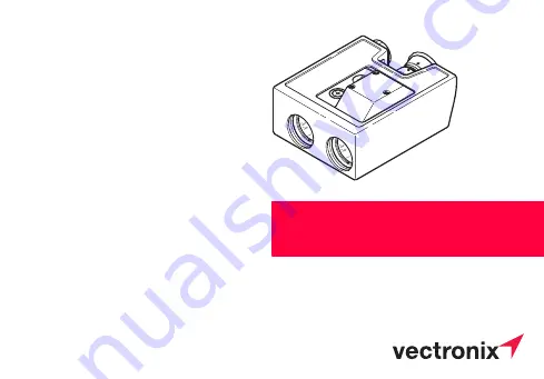
PLRF10C / PLRF15C
User Manual
English, Version 2.0III 2008
Pocket Laser Range Finder with
Compass
Страница 1: ...PLRF10C PLRF15C User Manual English Version 2 0 III 2008 Pocket Laser Range Finder with Compass...
Страница 2: ...he PLRF10C 15C is a pocket size handheld button operated laser rangefinder with integrated digital magnetic compass and sighting optic The PLRF10C 15C is capable to provide distance azimuth and inclin...
Страница 3: ...he batteries 12 Diopter adjustment 13 Reticle 14 General Operations 15 Distance Measurements 16 Factors affecting measurement range 16 Complete measurement with data transfer slope distance azimuth in...
Страница 4: ...t 23 Configuration 24 Making adjustments 24 Measuring 3 distances 25 Electronic reticle 25 Night vision device 25 Night vision operation Mount 26 Night vision operation Remove 27 Settings 28 Measureme...
Страница 5: ...ion 35 Results 36 Built in Test 37 Troubleshooting 38 Data transfer 42 Connecting the interface cable 42 Data transfer format to PC PLGR and GARMIN 43 Equipment 44 Parts List 44 Accessories 45 Options...
Страница 6: ...ided 7 x 50 binocular 0 meter Intended purpose The device is designed as a navigation aid it can be used in addition to other instruments or techniques must never be used as a sole navigation instrume...
Страница 7: ...gs the risk of injuries instrument errors damage to property malfunction Blinding hazard Do not look into powerful light sources with the device Do not open the device The built in laser can cause eye...
Страница 8: ...spectacle lenses do not use any solvent except water e g no alcohol or cleansers Lens cleaning Particles of dirt should be blown off or removed using a soft brush Finger prints may be cleaned first by...
Страница 9: ...d of view 106mil 6 Focus fixed Dioptric setting 2dpt to 4dpt Magnetic Compass azimuth and inclination Azimuth range 360 6400mil Accuracy 1 Azimuth 10mil 0 6 Inclination 3mil 0 2 Display resolution 1 1...
Страница 10: ...C PLRF15C Laser type IR diode 905 nm 1550 nm Eye safety Class 1 Class 1 Standard IEC60825 1 Ed 1 2 2001 08 IEC60825 1 Ed 1 2 2001 08 Range Performance 5m 2500m 5m 3000m Specified Performance 1800m 250...
Страница 11: ...ents Immersion 1m 30min Operational temperature range 35 C to 63 C 31 F to 145 F Storage temperature range without battery 40 C to 85 C 40 F to 185 F Weight with batteries and rubberized cover 670g 1...
Страница 12: ...ry cover Tighten it completely until it stops The device monitors the condition of the batteries If the display shows LobA this indicates that the batteries are used up You can still get readings but...
Страница 13: ...2 0en 13 Diopter adjustment Sight on an object farther than 100 m away and rotate the eyepiece to obtain a sharp image Standard setting 0 L If the device is being used by different people remember yo...
Страница 14: ...reticle can be used in place of the electronic aiming mark Line spacing 10 mils Line point spacing 5 mils L 1 mil corresponds to 1 m spacing at a distance of 1 km Electronic reticle An illuminated ai...
Страница 15: ...tion is indicated by the following symbols press and hold key release key press and release key click L You can prolong the display period by holding down the range key while the result is displayed 2...
Страница 16: ...ce Measurements PLRF10C 15C 2 0en 16 Distance Measurements Factors affecting measurement range Reflective properties Size of the target Oblique surfaces Atmospheric conditions Vibration Lighting condi...
Страница 17: ...rument steady as you release the key dIS appears briefly followed by the slope distance is displayed when no distance could be detected While the display is on press and hold the distance key to get t...
Страница 18: ...ated in the config uration menu see page 24 A flashing display after dIS indicates that more than one distance has been detected Press and hold the distance key repeatedly to scroll through all obtain...
Страница 19: ...t with the aiming mark Click the azimuth key 0 5s while holding the device steady The first object measurement is confirmed with 1 P first point Sight the second object with the aiming mark Release th...
Страница 20: ...ly press and hold it down Sight the object with the aiming mark Release the distance key while holding the device steady The horizontal distance is displayed indicated with Hd Press and hold distance...
Страница 21: ...ilar to a magnetic compass Metal objects magnetic fields and electronic devices e g radio can cause error in directional readings Nonmagnetic metals and alloys do not affect the compass readings L Cou...
Страница 22: ...Press and hold the azimuth key AZi appears for a short instance followed by the current azimuth The display updates continuously Sight the object with the aiming mark then release the azimuth key whil...
Страница 23: ...y once then immediately press and hold it down Inc appears for a short instance followed by the current inclination The display updates continuously Sight the object with the aiming mark then release...
Страница 24: ...lick the distance key five times in rapid succession ConF appears for a short instant Click the azimuth key until the desired function status appears L The various functions are described in detail on...
Страница 25: ...single measurement see page 18 Electronic reticle Function ErOn Er OF ErOn activates the electronic aiming mark which is useful for poor lightning conditions Night vision device Function ntOn ntOF nt...
Страница 26: ...he configura tion menu see page 24 25 Set the diopter to 0 Turn the eyecup inside out 1 Attach the night vision adapter 2 Tighten the screw 1 Rotate the lens on the night vision device to infinity pos...
Страница 27: ...rew and remove night vision adapter 2 Turn the eyecup outside in Set ntOF in the configuration menu for use without night vision device see page 24 25 L If the function is set to ntOn and the device i...
Страница 28: ...k the azimuth key five times in rapid succession Unit appears briefly Click the distance key until the desired unit appears Click the azimuth key five times in rapid succession to store the selection...
Страница 29: ...AtE appears briefly followed by the current setting e g OFF Click the azimuth key until the desired minimum distance appears e g 300m Setting OFF disables the distance gate Click the distance key thre...
Страница 30: ...th enter the value 0 into the device Declination display Click the azimuth three times in rapid succession dECL appears briefly followed by the current setting OldC is displayed before the device swit...
Страница 31: ...lick on azimuth key to change between increasing 0 1 2 and decreasing 0 1 2 Short click on distance key the declination value changes by one unit per click Hold down distance key 0 5s the declination...
Страница 32: ...azimuth key eight times again to store the default factory settings Stor dEF Stor appears If not done correctly the settings remain unchanged and Old C is displayed The default factory settings are E...
Страница 33: ...sed to strong magnetic fields When metallic parts have been attached to the device e g night vision device After movement greater than 20km and or to a different terrain type After a temperature chang...
Страница 34: ...Tilt the left side of the device downwards undo undo tilt return to horizontal tFAr too far reverse direction Always turn in the same direction for all ro90 instructions Important When the StOP instru...
Страница 35: ...int compensation procedure L If you want to perform the 12 point compensation click the distance key until 12Pt is displayed The selected procedure starts automatically after a few moments Move the de...
Страница 36: ...esults After compensation the device acts on the measurement results as follows Acc mil Display Process 1 20 Good ACC xx The newly determined constants are stored 21 90 bAdC ACC xx The newly determine...
Страница 37: ...the built in test starts automatically The distance key can be used to scroll through the test Keeping the distance key pressed prolongs the display time 1 Model e g PLRF15C 2 Software version e g 01...
Страница 38: ...an battery contacts Low temperature reduces performance of batteries Warm up batteries Extreme heat shortens batteries life Do not store the batteries at temperature over 70 C is displayed after dista...
Страница 39: ...see page 29 The following symbols are displayed during azimuth measurements _ _ _ _ _ _ _ _ _ _ _ _ _ _ _ _ The allowed inclination and or tilt angle has been exceeded tilted too far upwards tilted t...
Страница 40: ...clination see page 30 31 Respect factors affecting azimuth measurement accuracy see page 21 Perform compass compensation see page 33 Perform compass compensation see page 33 Compass compensation can n...
Страница 41: ...ed object 3dOF is set in the configuration menu only the distance with the highest return signal is displayed Select 3dOn in the configuration menu see page 24 ntOn is displayed after a measurement Th...
Страница 42: ...erent possibilities Caution Incorrect handling can damage the socket or optional interface cable To plug 1 Remove protection cap 2 Align the respective mark ings on the plug and socket 3 Slide the plu...
Страница 43: ...C 2 0en 43 Data transfer format to PC PLGR and GARMIN Interface parameters Interface RS 232 Data transmission bidirectional Baud rate 9600 bps Parity none Data bits 8 Stop bits 1 Handshake none PC PLG...
Страница 44: ...extent of delivery Spare parts 1 PLRF10C PLRF15C 5 723 791 Eye cap 2 903 590 Rubberized cover 6 727 539 Battery cover 3 667 002 SEB51 lithium battery 3V CR123A 2x required 7 703 228 Protection cap fo...
Страница 45: ...706 271 SEV48 data cable to PC 2 721 951 SEV63 data cable to PLGR 3 902 984 SEV83 data cable to GARMIN 12 12XL 4 Night vision adapter PLRF upon request 5 664 868 SST3 1 mini tripod non magnetic 6 729...
Страница 46: ...ew followed by the current setting If IF doesn t appear no options are enabled Click the distance key until the desired interface setting appears The choice depends on enabled options The various sett...
Страница 47: ...eters RS232 and data transfer format see page 43 PLGr Setting for communication with PLGR 96 PLGR II DAGR Data transfer via PLGR cable GARM Setting for communication with GARMIN GPS 60 76 72 and 12 se...
Страница 48: ...he ANG reference Grid Select the datum which corresponds to the map being employed The proper datum must be selected Improper datum selection will result in poor target position accuracy Set the AUTOM...
Страница 49: ...ect the appropriate units METRIC Select die appropriate heading reference GRID and heading unit MILS Interface Setup Set the data protocol to GRMN GRMN Set the GARMIN GPS as HOST The proper datum must...
Страница 50: ...e azimuth key 0 5S while holding the device steady The first measurement is confirmed with 1 P Sight the Fall of Shot and release the distance key while holding the device steady The first correction...
Страница 51: ...e the display is on to obtain the last correction value UP for up dn for down The corrections are given from the Fall of Shot position Click distance key repetitive to obtain the corrections again Exa...
Страница 52: ...hone 41 71 726 72 00 Fax 41 71 726 72 01 Internet www vectronix ch Copyright Without the prior written permission of Vectronix this document may neither be copied in part or whole by mechanical photog...
Страница 53: ...anagement system that complies with international standards for quality and quality management systems ISO 9001 and environmental management systems ISO 14001 Total Quality Management our commitment t...
Страница 54: ...Code 903826 2 0en Printed in Switzerland Copyright by Vectronix AG Heerbrugg Switzerland III 2008 Vectronix AG CH 9435 Heerbrugg Switzerland Telephone 41 71 726 72 00 Fax 41 71 726 72 01 www vectronix...