background image


TCX2-40863 

P

RODUCT 

D

ATA 

S

HEET


Doc: 70-00-0174C, 20221118 

© Vector Controls GmbH, Switzerland 

Page 6-10 

Subjects to alteration  

www.vectorcontrols.com 

V

ECTOR


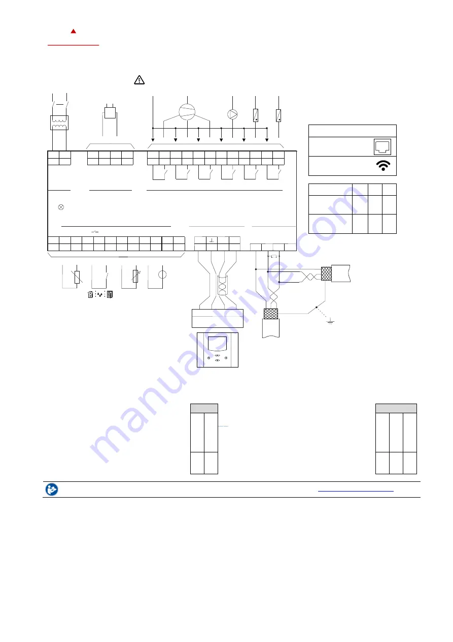
Connection diagram 


Configuration of in- and outputs 

The inputs and outputs are configured with jumpers. Jumpers are located underneath the controller. 

AO: Selection of analog output type 

Left position:  

voltage output (0... 10 V) 


factory default


Right position:  

current output (0... 20 mA) 

AO1 


UI: Selection of universal input type


Left position:  

voltage output (0... 10 V) 


factory default


Middle position: current input (0... 20 mA) 

Right position: RT or dry contact 

UI1 

0

1

0

V


0

2

0

m

A


0

1

0

V


0

2

0

m

A


R

T

 /

 D


See the TXC2-40863 installation sheet, document no. 70-00-0599 or 70-00-0884 (

www.vectorcontrols.com

). 

Status-LED 

The TCX2 has a status-LED which is located on the upper left side of the controller housing. 

The location of the LED is described in the installation sheet. The function of the LED is explained in the X2 Operations 

Manual. 

Reset button TCP/IP (-WEM, -WEB, -ETM, -ETB only) 

The TCP/IP configuration setting of the TCX2 can be reset by pressing the reset button with a 1 mm pin through the small 

hole located next to the Status-LED. The function of the TCP/IP reset is explained in the X2 Wi-Fi / Ethernet Configuration 

Manual. 


Relays 3A


N


L


A


c


t


u


-


a


t


o


r


Status LED


1


2


3


4


RS-485


Room Operating Unit


24V AC/DC


10 VA


AO 0...10 VDC


     0...20 mA


OPX-(2HT)-VC


Digital Output (6x)


Universal Input (8x) 

L


N


N


Q53


Q54


Q63


Q64


AO


GND


RT, 


DI (  )

0...10 VDC, 0...20 mA 

TX1


TX2


TX3


TX4


N


UI


UI


UI


UI


GND


GND


GND


GND


0...10 VDC


0...20 mA


NTC


10 k


Pot.


Vop


+


_


STP


120


(LT)


Line Termination (LT)


Shielded Twisted Pair (STP)


G0


 G 


GND


V+  


Power


Analog Output 

M


 Y1 


GND


 AO1  


Y2


 Y3 


AO2


AO3  


OP1


OP2  


OP3


OP4  


Q13


Q14


Q23


Q24


Q33


Q34


Q43


Q44


DO1


DO1


DO2


DO2  


DO3  


DO3  


DO4  


DO4  


DO5  


DO5  


DO6  


DO6  


M


X8


X7


GND


X3


M


X4


X5


X6


UI2


 X2


GND


GND


 UI1 


  M


 X1  


UI3


UI4


UI5


UI6


UI7


UI8


M


GND


N


Note: Power GND ≠ TX REF


TX3


-MOD


REF   


BACnet MS/TP


TX1


TX2


-BAC


+


RS-485


REF


(D0)


(D1)


MODBUS


+


Do not use shield as REF


-ETM, -ETB


Ethernet Connection 

TCP/IP 

-WEM, -WEB


WIFI Connection 

OPT1-xx 
OPA2-xx 

(-MOD), (-BAC) 

G0 = M = GND 

Содержание 40-110032

Страница 1: ...rol loops o Functions for dehumidifying set point shift and cascade control o Multiple auxiliary functions heat cool auto changeover automatic enable set point compensation o Free heating and cooling...

Страница 2: ...13 Modbus RTU or ASCII communication AEX BAC 40 500044 BACnet MS TP communication AEC SMA 01 40 500146 Antenna cable kit for external mounting of the Wi Fi antenna cable length 1 m AEC USB 01 40 50004...

Страница 3: ...00 VAC to EN 60 730 1 1250 VAC to EN 60 730 1 Electrical connections Connector type Removable connectors wire 0 34 2 5 mm2 AWG 24 12 Remote terminal RS485 in accordance with EIA TIA 485 Shielded twist...

Страница 4: ...4800 9600 19200 38400 Protocol Data bits Parity stop bit RTU 8 data bits ASCII 7 data bits no parity 2 stops even or odd parity 1 stop BACnet BAC Communication standard BACnet MS TP over RS485 BTL tes...

Страница 5: ...sheet document no 70 00 0599 or 70 00 0884 www vectorcontrols com Selection of sensors and actuators Temperature sensors Use Vector Controls NTC sensors to achieve maximum accuracy SDB Tn10 20 duct S...

Страница 6: ...explained in the X2 Operations Manual Reset button TCP IP WEM WEB ETM ETB only The TCP IP configuration setting of the TCX2 can be reset by pressing the reset button with a 1 mm pin through the small...

Страница 7: ...Mounting and installation manual OP MOD BAC TCX2 40863 Install Sheet TCP IP 70 00 0884 Mounting and installation manual WEM WEB ETM ETB X2 Operations Manual button display 70 00 0950 Operations instr...

Страница 8: ...ice management UTC Time synchronisation B DM RD B Device management Reinitialize device B Supported standard BACnet application services ReadProperty ReadPropertyMultiple WriteProperty DeviceCommunica...

Страница 9: ...tions AL 1AL to 8AL 8 Alarm conditions LP 1L to 4L 4 Control loops AO 1A to 3A 3 Analog outputs selectable with jumper mA VDC FAN 1F to 2F 2 Fan or lead lag modules 1 to 3 fan speeds up to 3 switching...

Страница 10: ...1118 Vector Controls GmbH Switzerland Page 10 10 Subjects to alteration www vectorcontrols com VECTOR Smart Sensors and Controls Made Easy Quality Innovation Partnership Vector Controls GmbH Switzerla...

Отзывы: