


7 Parameters of Image Processing
18 / 41
7
Parameters of Image Processing
This chapter explains the function of the IRC-320 firmware. It is related to the individual modules of
image processing and shows in what way the user can control these modules via the serial Interface.
7.1
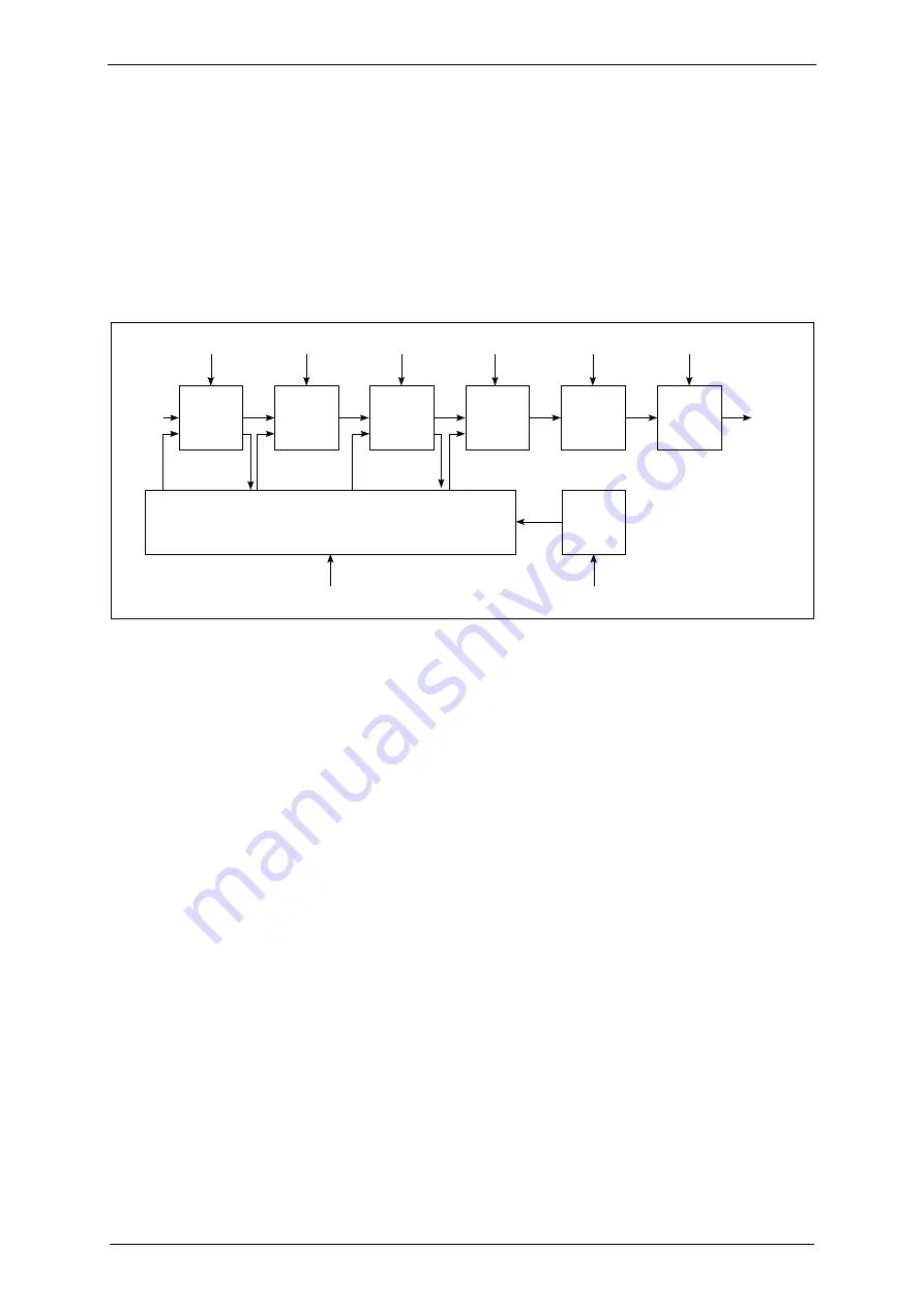
Image Processing Chain
Due to the fact that the uncorrected sensor image from the microbolometer sensor is very
inhomogeneous and that each sensor element has its own characteristic curve, an individual
adjustment of each pixel is necessary. The standard firmware of the IRC-320 contains a chain of
correction modules which undertake these tasks in real time.
LUT
Integrator /
Image Store
Two Point
Correction
Bad Pixel
Correction
Drift
Compensation
Output
(CL, GigE)
Input
(Camera
Raw Data)
E,J,K,N
F
m,n,o,p
H
Correction Data
Memory Access Module
S
(C)
(A,B)
(H/U,A,B)
(H/U)
Flash Memory
Access Module
A,B,C
Background
Subtr
Integrator /
Image Store
M,U
(U/H)
(U/H)
D,G
Each module can have various parameters which control the operation mode. In the sketch above and
as well within the text of this manual, these parameters are always marked by “
Courier
” font in
order to highlight them to be parameters (or commands) adjustable via the serial Interface.
For fast access all available correction data (e.g. reference images for the two point correction and bad
pixel correction control data) are copied from the non-volatile flash memory into a correction data
memory (SDRAM) when starting the camera. From this point the correction data is available for real-
time image correction. The image data from the camera head is shifted through the correction modules
and the corresponding correction data is applied. Some modules may also write new data back to the
correction memory – but currently only to the SDRAM and not to the non-volatile Flash memory.
The main correction modules are in detail:
1.
Two Point Correction
2.
Background Correction
3.
Bad Pixel Correction
4.
Drift Compensation
5.
Look Up Table (LUT)
With help of the
two point correction
(likewise “Gain Offset Correction”) the normally distinctive
underground structure of the microbolometer sensor can be equalized. The gain and the offset for each
pixel of the input image can be adapted to the set values on the basis of two reference images so that in
the optimum case no image structure is discernible.
The IRC-320 models feature an electromechanical shutter. In conjunction with the second correction
module in the chain – the
background correction
– the image quality can additionally be enhanced.
The shutter is closed to acquire a temporary background correction image. This image is subtracted
from the two point corrected image data to reduce the remaining fixed pattern noise.
VDS Vosskühler GmbH
IRC-320