


Series 590
OPERATION
298292EB
Edition 2013-05-13
41/56
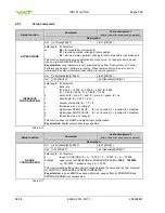
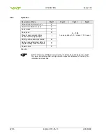
5.6
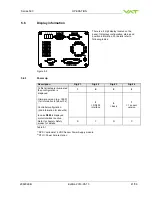
Display information
There is a 4 digit display located on the
panel. It displays configuration, status and
position information. For details refer to
following tables.
Figure 5-2
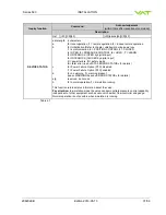
5.6.1
Power up
Description
Digit 1
Digit 2
Digit 3
Digit 4
At first all dots are illuminated
then configuration is
displayed:
Firmware version [e.g. 1E00]
(1st information for about 3s)
Controller configuration
(2nd information for about 3s)
In case
D999
is displayed,
motor interlock is active.
Refer to chapter «Safety
mode» for details.
1
E
0
0
2
= RS232
Interface
0
= basic
1
= 1 sensor
version
S
Y
N
C
Table 5-1
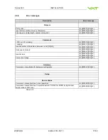
1)
SPS = optional ±15 VDC Sensor Power Supply module
2)
PFO = Power Failure Option
1 2 3 4


