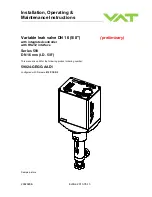


Series 590
INSTALLATION
298292EB
Edition 2013-05-13
15/56
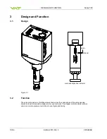
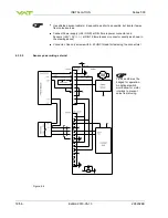
4.2.3
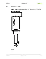
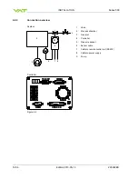
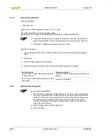
Installation procedure
1. Remove protection flanges only prior assembly into the vacuum system.
2. Install valve [1] into the vacuum system.
The valve seat side is indicated by the symbol «
∆» on dimensional drawing, see
Do not admit higher forces to the valve than indicated under «Admissible forces».
Make sure that enough space is kept free to do preventive maintenance work.
The required space is indicated on the dimensional drawing.
3. Install the sensor [5] according to the recommendations of the sensor manufacturer and directives
given under «Requirements to sensor connection».
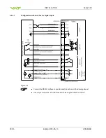
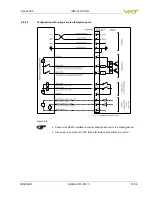
4. Connect pressure sensor cable [6] to sensor and then to valve (connector: SENSOR). Refer to
chapter «Electrical connection» for correct wiring. 59024-GEGG-0001 supports 1 sensor.
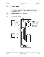
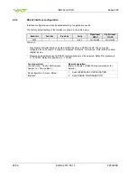
5. Connect valve to RS232 [7] (connector: INTERFACE). Refer to «RS232 schematics» for correct
wiring.
6. Connect power supply [8] to valve (connector: POWER). Refer to chapter «Electrical connection»
for correct wiring.
To provide power to the valve motor pins 4 and 8 must be bridged, otherwise motor
interlock is active and thevalve enters the safety mode and is not operative. Refer
also to «Safety mode».
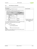
7. Perform «Setup procedure» to prepare valve for operation.
Without performing the setup procedure the valve will not be able to do pressure
control.
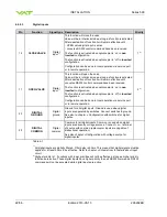
4.2.4
Admissible forces
NOTICE
Force at valve body and flange
Forces from the weight of other components can lead to deformation of the valve body
and flanges.
Do not apply any force at valve body or flanges.
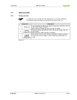
4.2.4.1
Admissible forces at controller
NOTICE
Force at controller
Forces from the weight of other components can lead to deformation the controller.
Do not apply any force at controller.


