Liquid Level Indicator
44
Installation and Operations Manual
Float Installation
1. Refer to appropriate tank configuration and install top anchors less long nipple and cap.
2. Thread the float guide cables into the tank through the top anchor fittings and pull the
ends back through the inspection hatch.
3. Fasten the bottom anchor to the guide cables (see Figure 18 on page 38) and lower the
anchor slowly through the inspection hatch into the tank.
4. When anchor bar is resting on tank bottom, remove cable slack by hand. Tighten cable
locking nut to secure cable in place.
5. Tighten the adjustment nut until the guide cable is tensioned by the spring. Trim excess
cable.
6. Use pipe thread compound and install top anchor nipples and cap.
Note
Throughout these instructions the term “tape/cable” is used to designate either
the indicator cable drive or the combination tape and cable drive that is used to also drive
the accessory drive elbow. If the tape/cable combination is used, the cable end goes on
the gaugeboard side.
Caution
If the tape/cable binds in the pipe during threading, check the pipe for corrosion
and other obstructions. Check the tape/cable to make certain that it did not kink. Friction
in the pipe will affect accuracy and may break the tape/cable.
7. Thread the tape/cable through the horizontal pipe and into the gaugeboard connector
pipe.
8. Put a clean drop cloth on the ground and push the tape through a few turns at a time from
the drop pipe elbow, until the tape/cable is unrolled. Make sure that the tape/cable falling
to the ground does not become kinked or dirty.
9. Use the tank bench mark as a guide and pull back enough tape/cable to drop from the
bench mark to the tank bottom. Mark that position on the tape for reference.
10. Thread the tape through the drop pipe into the tank and pull the end back through the
inspection hatch.
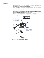
11. Install the tape/cable to the float connector with the clamps and screws provided (see
12. Attach the tape/cable connector to the float, pass it through the hatch and attach the eyes
to the guide cables.
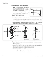
13. Attach the grounding wire to the float as described in Connecting the Tape to the Float on
Caution
Do not allow the float to fall to the surface of the product. Damage may result.
14. Lower the float until it is hanging from the tape/cable. Inspect the tape/cable and cables
for twists and kinks. Make sure that the cables are parallel, then lower the float to the sur
-
face of the product.
15. Make a hand gauge measurement of the tank product level. Use the bench mark reference
to calibrate the hand gauge. Use extra care to make certain that this measurement is accu
-
rate because the accuracy of the sight gauge indicator depends upon it.
16. If an accessory is to be installed, perform the installation. Refer to the main text auxiliary
equipment installation paragraphs and then continue the installation. The hole size, bolt
Содержание 6700
Страница 2: ......
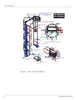
Страница 24: ...Liquid Level Indicator 16 Installation and Operations Manual Figure 7 Cone Roof Tank Installation 12 50 318...
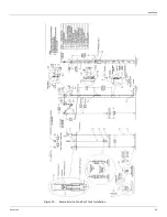
Страница 25: ...Installation Varec Inc 17 Figure 8 Half Travel Cone Roof Tank Installation 16 50 419...
Страница 31: ...Installation Varec Inc 23 Initial Lubrication Apply a light oil to the elbow and indicator sheaves...
Страница 37: ...Installation Varec Inc 29 Initial Lubrication Apply a light oil to the elbow and indicator sheaves...
Страница 39: ...Installation Varec Inc 31 Figure 15 Bolted Tank Installation 16 50 419...
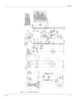
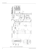
Страница 51: ...Installation Varec Inc 43 Figure 20 Severe Service Cone Roof Tank Installation 12 50 318...
Страница 70: ...Liquid Level Indicator 62 Installation and Operations Manual...
Страница 73: ......


