Liquid Level Indicator
28
Installation and Operations Manual
Initial Calibration
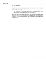
These instructions apply to systems that use a hollow-shell, welded float that is 14.5 inches
[368 mm] in diameter by 4.0 inches [102 mm] deep. Calibration is based upon the standard
specific gravity of water (1.0).
Note
For products of other specific gravities to be gauged, adjust the indicator accord
-
ingly. Refer to the industry related charts for the particular product.
With the float just touching the bottom of the tank, water will be at the float equator (water
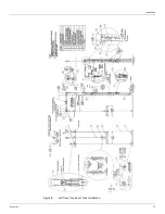
line). Set the gaugeboard indicator to 2.00 inches [50.8 mm]. Use the float connecting clamps
(see Figure 8 on page 17) to make the final adjustment, then trim excess tape or cable at the
float end, leaving some additional tape or cable for future adjustment needs.
Содержание 6700
Страница 2: ......
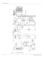
Страница 24: ...Liquid Level Indicator 16 Installation and Operations Manual Figure 7 Cone Roof Tank Installation 12 50 318...
Страница 25: ...Installation Varec Inc 17 Figure 8 Half Travel Cone Roof Tank Installation 16 50 419...
Страница 31: ...Installation Varec Inc 23 Initial Lubrication Apply a light oil to the elbow and indicator sheaves...
Страница 37: ...Installation Varec Inc 29 Initial Lubrication Apply a light oil to the elbow and indicator sheaves...
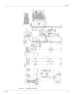
Страница 39: ...Installation Varec Inc 31 Figure 15 Bolted Tank Installation 16 50 419...
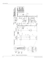
Страница 51: ...Installation Varec Inc 43 Figure 20 Severe Service Cone Roof Tank Installation 12 50 318...
Страница 70: ...Liquid Level Indicator 62 Installation and Operations Manual...
Страница 73: ......

