Installation
Varec, Inc.
13
Installation of Oil Seal, 27-Inch Water Column Operating Pres
-
sure
Refer to Figure 4 on page 6.
1. Apply thread pipe compound and install short pipe (3) into 180-degree elbow (1).
2. Apply pipe thread compound and install 180-degree elbow (4) onto short pipe (3).
3. Apply pipe thread compound and install long pipe (2) into elbow (4).
4. Apply pipe thread compound and install 90-degree elbow supplied with gauge kit onto
long pipe (2).
5. Complete the assembly to the user furnished 1.5-inch pipe.
6. Adjust the assembly to provide the tape/cable path as illustrated.
7. Proceed with the remainder of the tank installation to the paragraph Initial Lubrication,
then fill the oil seal as follows:
a. See Chapter 4, Maintenance, for oil selection.
b. Remove the cover from 90-degree elbow.
c. Fill to halfway in the short pipe.
Note
To drain the oil, open the plug in 180-degree elbow (4).
Cone Roof Tank Installation
Note
Be sure to read General Preparation at the beginning of this section before pro
-
ceeding with this installation.
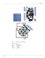
Refer to Table 6 on page 10. See Figure 7 on page 16 for full travel or Figure 8 on page 17 half
travel Liquid Level Indicators.
1. Determine the position on the tank roof, beneath which the center of the float will rise and
fall. Notice that this position is located a minimum of 16 inches [406 mm] and a maximum
of 36.00 inches [914 mm] from the wall of the tank.
2. Provide the roof holes shown in the figure, centered on this position. The float diameter is
14.50 inches [368 mm]. The guide cable holes are centered 8.50 inches [216 mm], each
side of the center of the float. The indicator cable pipe is centered on a 17.00 inch [432
mm] diameter.
3. Check the angle of the roof.
4. Connect a pipe coupling to the 1.5-inch vertical pipe that is to be attached to the roof and
hold it plumb while welding the coupling into the hole in the roof. Failure to place the cou
-
pling and pipe in a true vertical position may affect the accuracy of the Liquid Level Indica
-
tor. Make sure that the interior of all pipes are clean and corrosion free.
5. After the coupling and pipe are checked to make certain that they are plumb, unscrew the
pipe from the coupling.
6. Seal the threads with pipe thread compound and reconnect the pipe to the coupling.
Содержание 6700
Страница 2: ......
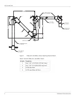
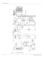
Страница 24: ...Liquid Level Indicator 16 Installation and Operations Manual Figure 7 Cone Roof Tank Installation 12 50 318...
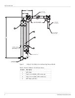
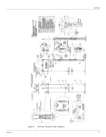
Страница 25: ...Installation Varec Inc 17 Figure 8 Half Travel Cone Roof Tank Installation 16 50 419...
Страница 31: ...Installation Varec Inc 23 Initial Lubrication Apply a light oil to the elbow and indicator sheaves...
Страница 37: ...Installation Varec Inc 29 Initial Lubrication Apply a light oil to the elbow and indicator sheaves...
Страница 39: ...Installation Varec Inc 31 Figure 15 Bolted Tank Installation 16 50 419...
Страница 51: ...Installation Varec Inc 43 Figure 20 Severe Service Cone Roof Tank Installation 12 50 318...
Страница 70: ...Liquid Level Indicator 62 Installation and Operations Manual...
Страница 73: ......

