


4 Wiring
Varec, Inc.
29
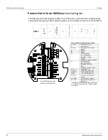
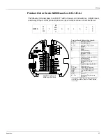
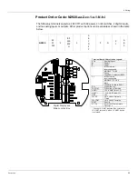
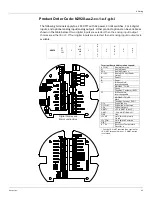
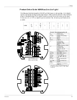
Product Order Code: N2920-aa-1-cc-0-N-2-g-h-i
The following terminals apply to a 2920 FTT with DC power, no limit switches, 4 digital inputs,
and optional analog input/analog outputs. Other product options can be variable as shown in
the table below.
N2920
AT
FC
FM
1
BP
MB
MS
LJ
0
N
2
N
A
B
C
0
1
A
B
C
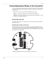
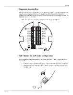
Digital Display and
Main Junction Box
Terminal Board Abbreviation Legend:
A COM
Analog Common
AI Analog
Input
AOx
Analog Output
A +24 V
24 Volt Power Output
B+ Power
+
B- Power
-
C 1
Bi-Phase Mark: Interchangeable
MODBUS: -TX/-RX
Space
TankWay: Computer (RXD)
C 2
Bi-Phase Mark: Interchangeable
MODBUS: +TX/+RX
Mark
TankWay: Encoder (TXD)
D I x
Digital Input x
D I COM Digital Input Common
DOxx Digital Output
HART+*
+ Ex d HART (Non-I.S. models)
HART-*
-
Ex
d
HART
(Non-I.S.
models)
R T D x
Resistance
Temperature
Detector x
* See the I.S. HART Junction
Box section for
I.S. HART terminals, when I.S. HART option
is selected.
Содержание 2920
Страница 2: ......
Страница 16: ...2920 Float Tape Transmitter 1 Introduction 6 Installation and Operations Manual...
Страница 114: ...2920 Float Tape Transmitter 6 Bi Phase Mark 104 Installation and Operations Manual...
Страница 120: ...2920 Float Tape Transmitter 7 MODBUS 110 Installation and Operations Manual...
Страница 126: ...2920 Float Tape Transmitter 9 L J TankWay 116 Installation and Operations Manual...
Страница 138: ...2920 Float Tape Transmitter 11 Configuration Calibration Level Limits and Outputs 128 Installation and Operations Manual...
Страница 148: ...2920 Float Tape Transmitter 12 Maintenance and Troubleshooting 138 Installation and Operations Manual...
Страница 158: ...2920 Float Tape Transmitter 14 Ordering Information 148 Installation and Operations Manual...
Страница 178: ...2920 Float Tape Transmitter MODBUSAppendix A MODBUS Implementation 168 Installation and Operations Manual...
Страница 193: ......