


Varec, Inc.
17
Chapter 4
Wiring
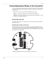
This chapter describes how to connect wiring terminations for the 2920 FTT. Wiring should be
done after the unit is mounted as described in "Mounting".
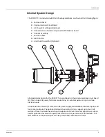
Overview
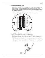
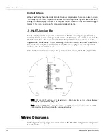
The wiring of the junction boxes to the 2920 FTT varies based on the order options. The 2920
FTT will be configured with additional junction boxes depending on the ordered options. The
maximum number and arrangement of junction boxes is shown in the following figure.
The following figure shows a typical mounting arrangement with the Varec 2500 gauge.
I.S. HART
Junction Box
Expansion
Junction Box
Junction Box
I.S. HART
Digital Display &
Main Junction Box
Expansion
Junction Box
Digital Display &
Main Junction Box
Содержание 2920
Страница 2: ......
Страница 16: ...2920 Float Tape Transmitter 1 Introduction 6 Installation and Operations Manual...
Страница 114: ...2920 Float Tape Transmitter 6 Bi Phase Mark 104 Installation and Operations Manual...
Страница 120: ...2920 Float Tape Transmitter 7 MODBUS 110 Installation and Operations Manual...
Страница 126: ...2920 Float Tape Transmitter 9 L J TankWay 116 Installation and Operations Manual...
Страница 138: ...2920 Float Tape Transmitter 11 Configuration Calibration Level Limits and Outputs 128 Installation and Operations Manual...
Страница 148: ...2920 Float Tape Transmitter 12 Maintenance and Troubleshooting 138 Installation and Operations Manual...
Страница 158: ...2920 Float Tape Transmitter 14 Ordering Information 148 Installation and Operations Manual...
Страница 178: ...2920 Float Tape Transmitter MODBUSAppendix A MODBUS Implementation 168 Installation and Operations Manual...
Страница 193: ......