


1 Introduction
Varec, Inc.
3
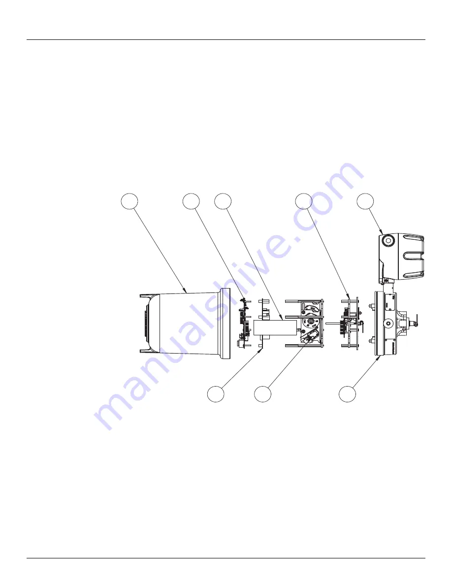
Internal System Design
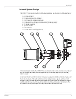
The 2920 FTT is constructed with the following assemblies, as shown in the following figure:
A. Enclosure Cover
B. Communications Circuit Board
C. AC Power Circuit Board (Optional)
D. Connector Circuit Board or Optional HART IS Barrier Board
E. Encoder Assembly
F.
Enclosure Base
G. Junction Box
H. Limit Switch Assembly (Optional)
All standard electronics for the 2920 FTT are contained on the communications circuit board
(B). This includes DC power, field communications, a 3-wire temperature input, and two
discrete inputs.
An optional circuit board (C) contains an AC power supply, two additional discrete inputs, and
four contact outputs. The optional limit switch assembly (H) can support up to four limit
switches. These limit switches and inputs/outputs can be used in safety applications such as
overfill protection, level switch inputs, local alarm control, permissives, and interlocks. The
limit switches and inputs/outputs can also provide basic automation control.
D
C
G
A
H
E
B
F
Содержание 2920
Страница 2: ......
Страница 16: ...2920 Float Tape Transmitter 1 Introduction 6 Installation and Operations Manual...
Страница 114: ...2920 Float Tape Transmitter 6 Bi Phase Mark 104 Installation and Operations Manual...
Страница 120: ...2920 Float Tape Transmitter 7 MODBUS 110 Installation and Operations Manual...
Страница 126: ...2920 Float Tape Transmitter 9 L J TankWay 116 Installation and Operations Manual...
Страница 138: ...2920 Float Tape Transmitter 11 Configuration Calibration Level Limits and Outputs 128 Installation and Operations Manual...
Страница 148: ...2920 Float Tape Transmitter 12 Maintenance and Troubleshooting 138 Installation and Operations Manual...
Страница 158: ...2920 Float Tape Transmitter 14 Ordering Information 148 Installation and Operations Manual...
Страница 178: ...2920 Float Tape Transmitter MODBUSAppendix A MODBUS Implementation 168 Installation and Operations Manual...
Страница 193: ......