background image

6.3 Surface mount

A

Mount the surface mount collar on the wall using the fixing kit supplied in the box. 

B

Place the reader/keypad onto the surface mount collar and clip down into place.   

C

Use the security screw supplied to attached the unit to the surface mount collar. 

D

Place the cap onto the unit and push firmly in place.

6.4 Flush mount

A

Remove spacers before mounting.

B

Prepare        the mounting surface to receive sub-surface       terminals.

Mount the flush mount collar on the wall       using the fixing kit supplied in the box. 

C

Place the reader/keypad onto the surface mount collar and clip down into place.    

ACT 5e prox – Installation and Operating Instructions

Wiring and Mounting Diagrams

© Vanderbilt 2019

15

A-100512-e

25.06.2019

Содержание ACT 5e

Страница 1: ...ACT 5e prox Installation and Operating Instructions Document ID A 100512 e Edition date 25 06 2019 ...

Страница 2: ... to make them available to any third party without our prior express written authorization nor to use it for any purpose other than for which it was delivered to him Hereby Vanderbilt International IRL Ltd declares that this equipment type is in compliance with the following EU Directives for CE marking Directive 2014 53 EU Radio Equipment Directive Directive 2011 65 EU Restriction of the use of c...

Страница 3: ...9 5 5 Set relay combinations 10 5 6 Delete user s card 10 5 7 Delete card number 10 5 8 Check if user has no PIN assigned 10 5 9 Check if user has no card assigned 11 5 10 Program ACT 5e prox options 11 5 11 Restore factory defaults 11 6 Wiring and Mounting Diagrams 13 6 1 ACT 5e prox wiring diagram for strike lock 13 6 2 ACT 5e prox wiring diagram for mag lock 14 6 3 Surface mount 15 6 4 Flush mo...

Страница 4: ...r on even if a card is lost or a user forgets their PIN code A valid card or PIN will allow access For maximum security the unit may be programmed to require all users to enter a PIN code after presenting a card 1 1 Product specification Number of Users 128 128 PINs and 128 Cards Supply Voltage 12 24V AC or DC linear PSU Current Consumption 60mA nominal 100mA maximum Operating Temperature 40 to 50...

Страница 5: ...ces l Never use the on board relay to switch AC mains voltage An external relay electrically isolated from the ACT 5e prox should be used for this purpose l Remember to change the programming code l When ordering new cards or fobs specify ACTRFID Note ACT 5e prox will NOT work with HID cards or fobs As with any access control system always ensure there is an alternate means of escape in the event ...

Страница 6: ... User 1 s card twice 4 Change Programming Code On the digital keypad press 0 Input Input the new programming code 4 digits 5 Exit Programming Mode On the digital keypad press The LED turns red and programming mode is exited 6 Record User Code and Card Enter the details of the Users and their associated codes and card numbers on the User List at the back of this manual The ACT 5e prox is now ready ...

Страница 7: ...ombinations Off Timed Relay 2 Set Door Relay Time 5 seconds 5 Add User Card 6 Delete User s Card 7 Delete Card Number 30 Card or PIN On 31 Card and PIN Off 32 Card and any PIN Off 40 Permanent Backlight On 41 Auto Backlighting Off 80 Check PIN User 81 Check Card User Vanderbilt 2019 7 A 100512 e 25 06 2019 ...

Страница 8: ...ntry Operation Example 1 0 Change PIN codes 0 Change PIN codes 2 000 127 Enter 3 digit User Number 000 127 007 User 7 3 0000 9999 4 digit code 0000 deletes user 7529 PIN code Remember to update the User List document at the back of this manual after adding a PIN or Card See User List on page 17 5 2 Add cards Enter programming mode then press Step Keypad Entry Operation 1 5 Add Card 2 000 127 First...

Страница 9: ...it programming Exit programming 5 3 Change programming code Enter programming mode then press Step Keypad Entry Operation 1 0 Change programming code Default 9999 2 3 0000 9999 New 4 digit programming code 5 4 Set door relay time Enter programming mode then press Step Keypad Entry Operation 1 2 Set door relay time Default 5 seconds maximum 255 seconds 2 0 1 0 Relay 1 1 Relay 2 Buzzer sounds indica...

Страница 10: ... 000 127 Last user to delete 010 User 10 5 7 Delete card number Enter programming mode then press Step Keypad Entry Operation 1 7 Delete card number 2 10 digit card number 10 digit Card number with leading zeroes E g for Card 54321 enter 0000054321 5 8 Check if user has no PIN assigned Enter programming mode then press Step Keypad Entry Operation 1 80 Check if user has no PIN already assigned 2 00...

Страница 11: ...Card and any PIN Off In this mode a valid card and any valid PIN code will open the door This mode allows all users to have a common PIN code to use with their cards 40 Permanent Backlight On When set the keypad illumination is always on This option will override option 41 Auto Backlighting 41 Auto Backlighting Off When set the keypad illumination is normally off but will switch on in response to ...

Страница 12: ...hout LK1 in place Defaulting memory takes 3 4 seconds During this time the buzzer will sound an elongated tone ACT 5e prox Installation and Operating Instructions ACT 5e prox Digital Keypad Programming Vanderbilt 2019 12 A 100512 e 25 06 2019 ...

Страница 13: ...ed locks If normally energised locks are required use the N C relay contacts l The ACT 5e prox may be powered from 12 or 24V AC or DC A Power up without link if programming code has been lost B IMPORTANT Always place varistor across lock terminals C Door Release button D Strike Lock 1 E Strike Lock 2 Vanderbilt 2019 13 A 100512 e 25 06 2019 ...

Страница 14: ...C relay contacts l The ACT 5e prox may be powered from 12 or 24V AC or DC A Power up without link if programming code has been lost B IMPORTANT Always place varistor across lock terminals C Door Release button D Magnetic Lock 1 E Magnetic Lock 2 ACT 5e prox Installation and Operating Instructions Wiring and Mounting Diagrams Vanderbilt 2019 14 A 100512 e 25 06 2019 ...

Страница 15: ...t collar D Place the cap onto the unit and push firmly in place 6 4 Flush mount A Remove spacers before mounting B Prepare the mounting surface to receive sub surface terminals Mount the flush mount collar on the wall using the fixing kit supplied in the box C Place the reader keypad onto the surface mount collar and clip down into place ACT 5e prox Installation and Operating Instructions Wiring a...

Страница 16: ...spacers are broken away by installer View B shows spacer stacking A Standard pattress box B C Attach the mounting plate to the pattress using the screws supplied C Ensure the correct spacers B have been used to bridge the gap between the mounting plate and the fixing wings of the pattress box to avoid the mounting plate being distorted D Place the reader keypad onto the surface mount collar and cl...

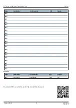
Страница 17: ...User List User User Name Card Number PIN Toggle 000 001 002 003 004 005 006 007 008 009 010 011 012 013 014 015 016 017 018 019 020 021 022 023 024 025 026 027 028 Vanderbilt 2019 17 A 100512 e 25 06 2019 ...

Страница 18: ...41 042 043 044 045 046 047 048 049 Example User User Name Card Number PIN Toggle 012 John Smith 0000200036 7529 No Download a PDF to record the full user list http van fyi Link 5eprox_UL ACT 5e prox Installation and Operating Instructions User List Vanderbilt 2019 18 A 100512 e 25 06 2019 ...

Страница 19: ...erbilt International Ltd Clonshaugh Business and Technology Park Clonshaugh Dublin D17 KV 84 Ireland vanderbiltindustries com contact Vanderbilt 2019 Data and design subject to change without notice Supply subject to availability Document ID A 100512 e Edition date 25 06 2019 ...

Отзывы: