background image

28     

Powering ON / OFF

Powering ON / OFF

Printer

Turning the power ON

[1]

Close the front cover.

[2]

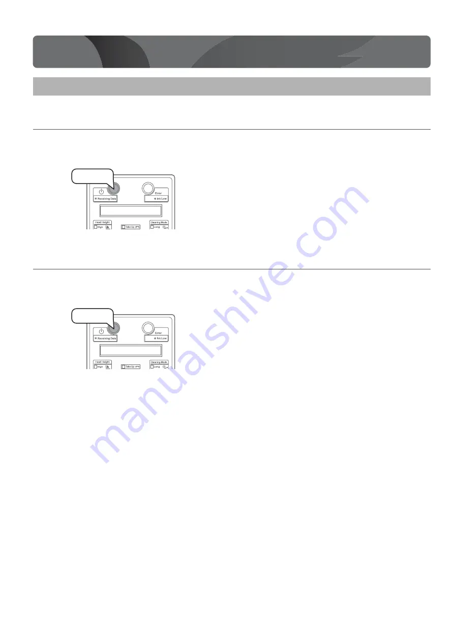
Press the power button to turn the power ON.

• The blue light becomes ON.

• This product starts its initialization operations.

Turning the power OFF

[1]

Make sure printing is done.

[2]

Press the power button to turn the power OFF.

• This product starts its powering off operations.

• The blue light becomes OFF.

Powering ON / OFF

Press!

Press!

Содержание MUTOH VJ-1938TX

Страница 1: ...ase contact MUTOH or the dealer you purchased the product from if you find any unclear erroneous or otherwise unsatisfactory content in the Guide Please be aware that MUTOH will not be liable in any w...

Страница 2: ...ations of unpacking and moving this product must be carried out by four or more persons working together Keep this product level when moving it Unpacking the printer 1 Open the packing box and take ou...

Страница 3: ...1 Cleaning stick 10 Installation Instruction Japanese English each Startup Guide this document Flushing box sponge 5 Tray 1 Media holder 2 Media setting plate 1 Paper towel 5 Waste fluid tank 1 Ink gu...

Страница 4: ...g the Take up System Unpacking or moving the Take up System must be done by at least two persons 1 Open the box and take out all components CAUTION Take up unit Feeding unit Media tube Accessory box R...

Страница 5: ...l adjusting screw 4 RearrollerAssembly 1 Feeding Unit 1 Pan head screw with spring washer and flat washer M4 12 16 Pan head screw with spring washer and flat washer M4 8 7 Media tube 1 Clamp small 5 C...

Страница 6: ...red items for installing and using the printer Note Items marked with an asterisk above are accessories or supplies Be sure to use a power cable of the specified type Using any other power cable could...

Страница 7: ...asher M4 8 from the tension unit weight fixing materials and then remove the two tension unit weight fixing materials 3 Remove the two screws Pan head screw with spring washer and flat washer M4 8 fro...

Страница 8: ...oller fixing material on the opposite side and remove it Feeding Unit 1 Remove the two screws Pan head screw with spring washer and flat washer 4 8 from the fixed shaft mounting plate and remove it 2...

Страница 9: ...5 Remove one screw each Pan head screw with spring washer and flat washer M4 8 from the tension unit weight fixing materials on the opposite side and then remove the two tension unit weight fixing mat...

Страница 10: ...Assemble the Take up System Assemble the Take up Unit and Feeding Unit Place wires Assemble the printer and stand Assemble the printer and stand Install the Rear roller Assembly Install the Take up U...

Страница 11: ...accessory 4 Assemble the left stand in the same way as in Step 2 3 5 Fasten the connector bar to the right stand using two hexagon socket head cap screws Attach the connector bar with the groove faci...

Страница 12: ...wn below to prevent the stand from moving 2 Insert the two transfer stays into theright and left transfer brackets lift the printer with four or more persons and place it on the stand 3 Remove the two...

Страница 13: ...the waste fluid tank 1 Place the waste fluid tank in the waste fluid tank holder 2 Attach the waste fluid tube to the tank 3 Insert the waste fluid sensor cable into the connector on the bottom of the...

Страница 14: ...Follow the procedure below to attach the clamp Procedure for attaching the clamp for the cable of the Take up System of the printer base 1 Attach the clamp large 2 Attach the clamp small 3 Attach the...

Страница 15: ...n place the tray 3 Open the front cover then remove a screw from the carriage fastening material metal plate and remove the fastening material 4 Peel off the tape be careful not to come in contact wit...

Страница 16: ...o screws Pan head screw with spring washer and flat washer M3 8 2 Attach the clamp small 2 Assembling the Feeding Unit 1 Attach one clamp large at the position of A Attach one clamp small at the posit...

Страница 17: ...form Make sure you have at least two persons when holding the rear roller assembly 2 Hook the rear roller assembly to the back of the printer 3 Temporarily fasten the rear roller assembly using seven...

Страница 18: ...oles of the stand four on each side a total of eight through the screw holes of the Take up Unit Do not hold the tension roller shown by the arrow A Place the front roll unit drive so that it is on th...

Страница 19: ...e same way as the front side place the Feeding Unit on the back of the stand Place the rear roll unit drive so that it is on the waste liquid tank side 2 Secure the Feeding Unit to the stand using eig...

Страница 20: ...the cable through the grommet Note The take up sensor cable is the cable that is coming out of the front tension unit Home side When you want to put the cable through under the rail in the illustratio...

Страница 21: ...n sensor to the controller board A Put the cable through the bottom clamp B Put the cable around the upper clamp once C Connect the cable connector to J13 on the controller board 7 Put the take up mot...

Страница 22: ...ft 2 Put the feeding motorcable label F_MOT through theclamps onthe path A Put the cable through two clamps on the rear tension unit The tip of the cable will come out on the side with the waste fluid...

Страница 23: ...met C Put the cable through one clamp on the path 7 Connect the cable to connect the Take up System with the printer to the controller board A Put the cable around the clamp on the path once B Connect...

Страница 24: ...se Installation location Minimum installation space Ensuring a suitable place for installation Keep the work area well ventilated The fumes from ink could adversely impact your health If you experienc...

Страница 25: ...re 20 C to 32 C Humidity 40 to 60 No condensation Recommended Printing Environment Temperature 22 C to 30 C Humidity 40 to 60 No condensation Printer Storage Environment Storage without ink charging u...

Страница 26: ...ote If the power switch is in a pressed inward state it is turned on and you must press it again to turn it OFF 2 Make sure that the Take up System is turned OFF Note The power switch to the Take up S...

Страница 27: ...clamps Important Put the power cable for the printer through the clamp on the leg as shown in the illustration Otherwise the rear roller may catch the power cable 5 Connect the power cable to the Tak...

Страница 28: ...button to turn the power ON The blue light becomes ON This product starts its initialization operations Turning the power OFF 1 Make sure printing is done 2 Press the power button to turn the power O...

Страница 29: ...System Turning the power ON 1 Press the power button to turn the power ON The green light becomes ON Turning the power OFF 1 Make sure printing is done 2 Press the power button to turn the power OFF T...

Страница 30: ...stall ink bags into this product and charge the print head with ink Print the nozzle check pattern and perform cleaning the head until all lines are clearly printed Connecting to a Computer Load the m...

Страница 31: ...nter key to confirm The cursor will move on to the next Confirm your input for each value Note Obtain the activation code from the distributor by email or other means 3 When the message on the left ap...

Страница 32: ...ructions displayed Step 2 Configuring the initial settings 1 Configuring the operation panel language and units 1 Press the key to select Lang English Press the Enter key 2 Press the Enter key 3 Press...

Страница 33: ...kCartridges is displayed Proceed to step 4 in this section The message on the left will appear 4 Open a new ink bag and shake it as described below Turn the ink plug upward and wait for three seconds...

Страница 34: ...atch the label of this product to the color of high capacity ink pack adapter Insert all the way to the end The message on the left will appear The printer starts ink charging During ink charging make...

Страница 35: ...k take up method You can take up the roll media without using the tension unit Use this method for the media that tend to have wrinkles from too much load when using the tension take up method This is...

Страница 36: ...ROLL When setting the outside roll media Note Inside roll media Media with the printable side on the inside Outside roll media Media with the printable side on the outside 7 Load the roll media to the...

Страница 37: ...en and secure the screw with a handle Put the media through the rear roller assembly 1 Move the MANUAL switch on the rear tension unit to the NORMAL side and pull the roll media out about 1 5 m 2 Put...

Страница 38: ...o the top over the rear roller B 5 Put the roll media from the bottom to the top over the rear roller C The media should be loaded to the roller as shown in the illustration when seen from the side Fo...

Страница 39: ...feed slot until the whole media setting plate is visible from the front side 4 Pull out the media setting plate from the front side Pull the media out several times until it reaches a length of about...

Страница 40: ...he roll media from the bottom to the top over the front tension unit s tension bar 4 Secure the roll media to the media tube using double sided tape Note For instructions on how to roll back the media...

Страница 41: ...The media should be loaded to the roller as shown in the illustration when seen from the side For the outside roll media For the inside roll media 5 Unhook the auxiliary media setting plate from B and...

Страница 42: ...on bar of the front tension unit and the media tube 2 Secure the roll media to the media tube using double sided tape Note For instructions on how to roll back the media during the setting operation r...

Страница 43: ...dia setting lever 3 Switch the front tension unit AUTO switch depending on how you set the media OUTSIDE ROLL When setting the outside roll media INSIDE ROLL When setting the inside roll media 4 Switc...

Страница 44: ...al Set 6 Output Mode P 80 3 Press the Forward key on the operation panel and take up about 2 to 3 rounds of the media to the media tube of the Take up Unit Note When Media End Take up Error is display...

Страница 45: ...e printed 5 Check the patterns If there is nozzle clog go to Cleaning steps P 48 If all lines are clearly printed you can start printing Note Before connecting to a computer to print configure the IP...

Страница 46: ...inter unused for an hour or more Then perform Little Charge again and check the print result If there is still no improvement contact your local Mutoh dealer 2 Cleaning steps 1 Press the Cleaning key...

Страница 47: ...t the accessory CD into the computer s CD ROM drive 2 Windows 10 Click Explorer in Start menu Windows 8 Windows 8 1 On the Start screen click Desktop Click Explorer Double click PC or Computer Windows...

Страница 48: ...nd CAUTION Meaning of symbols Important Notice The CE marking is a mandatory European marking for certain product groups to indicate conformity with the essential health and safety requirements set ou...

Страница 49: ...wer cord set Using a power cord set other than the specified can cause an electric shock or fire Use a power cable that is equipped with a protective grounding terminal and connect it firmly to the ou...

Страница 50: ...hold Reinforcement If lifting up the printer with the vinyl on there is a possibility the printer can slip and drop and be damaged Concerning handling Do not step on this printer or place heavy thing...

Страница 51: ...er cable of the printer Not to open the front cover Not to open the maintenance cover Not to raise the media setting lever Concerning consumable items You are obligated to properly dispose of waste fl...

Страница 52: ...s deux c bles d alimentation soient d branch s durant l entretien Do not bend or pull the waste ink drain tube The ink may be leaked and damages the printer CAUTION ATTENTION Ne pas tirer ou plier le...

Страница 53: ...3 Note The following marks are for China s safety standards P Dan hab yungh youq gij digih haijbaz 2000m doxroengz haenx ancienz sawjyungh Dan hab yungh youq gij dienheiq diuzgen mbouj dwg diegndat ha...

Страница 54: ...shown below Instruction labels 7 colors Slot 5 K Slot 8 Slot 7 Slot 6 Slot 5 Slot 6 Slot 7 Slot 8 4 colors M K M Y Y Bl Bl Y Media Path OUTSIDE ROLL Media Path INSIDE ROLL 7 colors Slot 1 M Slot 4 Sl...

Страница 55: ......

Страница 56: ...VJ1938TXE Q 04...

Отзывы: