


VALLOX 90 SE
Surface mounting
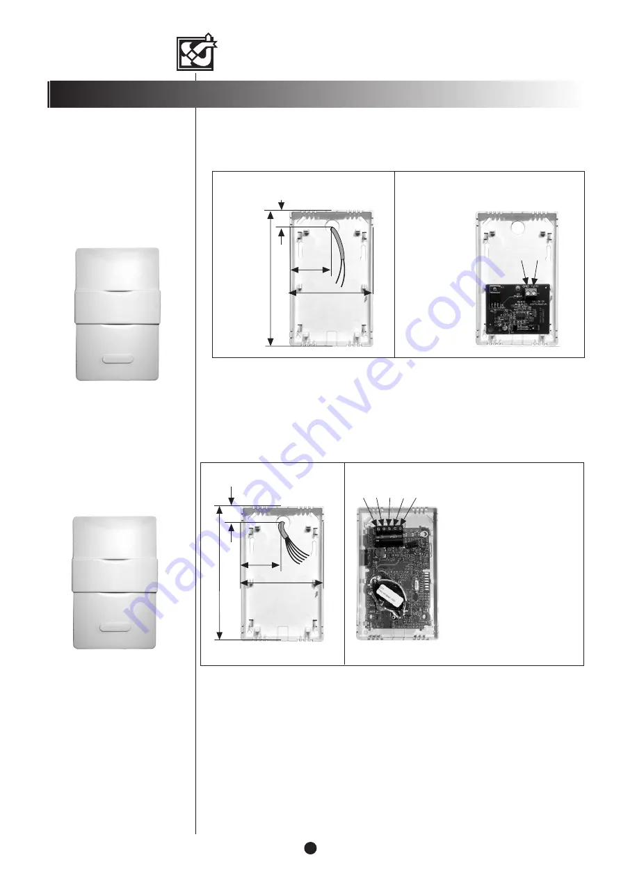
Wiring
Cable: 2 x 0.5 mm
2
Electronics board
of %RH sensor
Surface mounting
© VALLOX • We reserve the right to make changes without prior notification.
Base plate
of sensor
14
125
38
76
Mounting and wiring of humidity sensor
Mounting and wiring of carbon dioxide sensor
Base plate of the CO
2
sensor
14
125
38
76
Carbon dioxide sensors
• Carbon dioxide sensors are connected
individually.
• When the first carbon dioxide sensor has
been connected to the system, the unit is
switched on. After this, the unit gives the
sensor an address. Follow the same steps
for other carbon dioxide sensors.
Electronics board of the CO
2
sensor (model may vary)
Humidity sensors
• When mounting two or more humidity
sensors, connect them to the terminal
block of the connection box by
connecting the first humidity sensor to
%RH1, in place of the 6K8 resistor in
the terminal block (remove the resistor
in this case), and the second humidity
sensor to %RH2. See the electrical
diagram.
S +
6
MOUNTING OF SENSORS
The sensor is wired straight from the electrical connection box of the unit.
The CO
2
sensor is wired directly from the VALLOX 90 SE connection box, or it can be wired
in series with another CO
2
sensor or control panel (see External electrical connections on
page 11).
Wiring
Cable:
NOMAK 2 x 2 x 0.5 mm
2
+ 0.5 mm
2
NOTE!
Faulty coupling of the (+) wire destroys
the carbon dioxide sensor!
1 = orange 1
= +
2 = white 1
= -
3 = orange 2
= A
4 = white 2
= B
5 = metal
= signal ground M
ca. 21 VDC
}
1 2 3 4 5
+ – A B M