26
Annex
Thermo DC 200
13 Annex
The installation of the heater must be carried out according to the
instructions described in the EBA (Chapter 1-11), except for the devia-
tions described and illustrated on the following pages.
13.1. Differing installation instructions for Thermo DC
11126153_
Installation
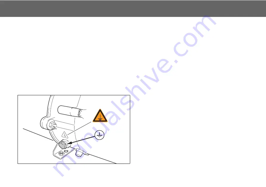
Additional potential equalization (PE)
A PE cable, at least 1x10mm² Cu, should be attached durable to the
position on the housing which is marked and provided for it. This is done
with a ring cable lug which is fastened with a M10x1 potential equaliza-
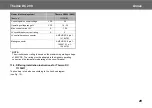
tion screw incl. washer (Fig. 12, for tightening torque, refer to Fig. 11).
The connecting screws on the heating appliance may only be replaced
with genuine original parts from Valeo, since these are part of the
electrical equipment and they ensure proper grounding.
486V DC supply line
The hook up must be made with at least a cable with 10mm² cross
section corresponding to the heater connection cable (HV). The cable
cross section must be chosen additional according to the power and
installed cable length. Use a dedicated power circuit for the heating
system.
The device must have a fixed connection to the DC power supply.
The heater must be connected to the potential equalization.
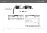
The connection must be carried out in accordance with the enclosed
hook-up diagram (see Figure 13).
ATTENTION:
When connecting the HV cable, it is essential to ensure the correct
current direction. A polarity reversal can lead to the destruction of
the heater.
Figure 12: Potential Equalization Screw
Содержание THERMO DC 200
Страница 1: ...Rev 05 2020 Id No 11118910E Installation and operating instructions THERMO DC 200 Bus HEATING SYSTEMS...
Страница 4: ...IV Thermo DC 200...
Страница 39: ...memos...


