background image

Unit Location

In general, the Dynacalibrator should be as close as possible to the analyzer to be 
calibrated, as long as:

•  the ambient temperature is at least 2°C below the selected operating  

temperature of the permeation chamber.

•  ambient temperature variations are minimal.

•  exposure to precipitation and condensation is minimized.

•  air flow around the unit’s cooling vents and rear panel fan intake is not 

blocked or restricted, particularly for the rack-mounted units.

•  it is on a level surface, to prevent errors in flow determination caused by a 

non-vertical flowmeter

When the Dynacalibrator is installed in an instrument rack, 
the user must make certain that the overall rack ventilation/
cooling is adequate.

A bench-mounted Dynacalibrator should be placed on a firm horizontal  
surface – preferably the same surface as the analyzer to be calibrated.  A rack-
mounted enclosure in a mobile installation (van, aircraft, etc.) requires additional 
mechanical support between the rack and the rear of the enclosure. This addi-
tional support is not needed for slide-mounted enclosures.

Once the Dynacalibrator has been unpacked and a location selected, check  
the packing slip included with the shipment to verify that all the ancillary parts 
(forceps, etc.) are available.  In the event of a discrepancy, please notify VICI  
immediately.

Permeation Device Conditioning

Dynacal permeation devices must be conditioned prior to their use in the  
Dynacalibrator.  Proper conditioning ensures that the device performs at its 
specified mass permeation rate and accuracy.

Conditioning is accomplished primarily by heating the device for a specified  
time period in a temperature-controlled environment (at the intended operating  
temperature ±1°C) through which there is a steady purge of dry gas at a  
minimum of 80 cc/min.

Since conditioning for each specific device is a function of a variety of factors, 
inflexible rules or recommendations cannot be included here.  Contact VICI 
Metronics for conditioning information for your permeation devices.

Getting Started

Содержание 500

Страница 1: ...s 713 688 9345 tech 713 688 8106 fax valco vici com VICI AG International Schenkon Switzerland Int 41 41 925 6200 phone Int 41 41 925 6201 fax info vici ch North America South America and Australia Oceania contact Europe Asia and Africa contact Manufactured by Valco Instruments Co Inc 8300 Waterbury Houston TX 77055 ...

Страница 2: ...Attention Radiant heat warning Entanglement warning Electrical warning Symbols used in this document ...

Страница 3: ...Supply Inlet 9 Span and Zero Outlets 9 Overflow Vent 9 Front Panel Controls and Indicators 10 Calculations 13 Initial Power Up 14 Connections 14 Chamber Temperature 14 Setting the Chamber Temperature Manually 15 Setting the Chamber Temperature Limit Switch 15 Setting the Chamber Temperature via Serial Port RS 232 16 Installing the Permeation Device s 16 Serial Port Communication 17 Setting Up Seri...

Страница 4: ...nd Cleaning 27 Carrier Flow Rate Verification 28 Dilution Flowmeter Calibration 28 Chamber Temperature Calibration 29 Troubleshooting 30 Electrical Troubleshooting 30 Pneumatic Troubleshooting 30 Leak Detection Fluid Method 30 Component Isolation Method 31 Model Number Breakdown 32 Warranty 33 ...

Страница 5: ...manual provides installa tion operation and maintenance information for all configurations of the Model 500 The identification tag on the rear panel of every Dynacalibrator is stamped with the unit s complete model number which reflects the exact unit configuration A chart on the last page of the manual explains the model num bers Basic Design The Model 500 contains three calibrated gas regulating...

Страница 6: ...tic The output of the permeation chambers is fed forward to SV1 and SV2 respec tively When the front panel switches are ON for SPAN 1 and or SPAN 2 then the respective carrier flows are routed through the valves C and NC ports and to the mixing tee where the calibrated dilution stream is added and mixed into it to set the final concentration When neither SPAN 1 nor SPAN 2 are selected both SV1 and...

Страница 7: ... SV1 opens to route carrier 1 flow to the mixing tee Differential pressure regulator DPR1 main tains a fixed 3 2 psi pressure differential across the selected flow control valve and meter The flow rate through the selected flowmeter is then a function of this fixed pressure differential and the carrier flow control orifice FR1 The desired dilution flow set using FCV2 is mixed with any selected per...

Страница 8: ...meters permits the user to accurately set both a low and high output concentration and switch between them and zero air for the three point check Options The following paragraphs provide general information on each with more detailed information found in Advanced Theory of Operation on page 24 Input Configurations The Dynacal 500 series is available with either single or dual gas supply Both plumb...

Страница 9: ... Introduction Specifications ...

Страница 10: ... or damage may result in the car rier refusing to honor any subsequent claim Unpacking the Dynacalibrator After the initial receiving inspection and check the Dynacalibrator may be unpacked A carefully sized and mated pair of shipping cartons have been designed to ensure against any damage to the Dynacalibrator while it is in transit Use the following procedures to remove the instrument from the p...

Страница 11: ...e equipment to VICI for inspection and repair When this work is completed the equipment will be returned to you with an invoice itemizing charges for all re pairs This invoice will become part of your claim to the carrier In the case of shipments made F O B destination VICI will at your request handle the filing of damage claims with the carrier provided an acceptable inspection report from the ca...

Страница 12: ...etc requires additional me chanical support between the rack and the rear of the enclosure This addi tional support is not needed for slide mounted enclosures Once the Dynacalibrator has been unpacked and a location selected check the packing slip included with the shipment to verify that all the ancillary parts forceps etc are available In the event of a discrepancy please notify VICI immediately...

Страница 13: ...with 1X input configurations separate carrier and dilution inlet ports are equipped with a supply inlet fitting The supply inlet must be connected to an external pressurized source of carrier and dilution gas such as an external pump a cylinder of compressed gas etc The most commonly used gas is dry air however dry nitrogen or any other comparably inert gas including ambient air may also be used T...

Страница 14: ...ently plumbed to the calibrate input port of an analyzer or temporarily connected to its sample input for calibration depending on the capabilities of the analyzer NOTE The span outlet port should be directly connected to the analyzer input with a minimum length of tubing Altering the output stream in any manner may affect the concentration of calibration gas in the stream OverflowVent All Dynacal...

Страница 15: ...ts when the main power switch is on The LED indicator lights when heater power is on A 4 amp circuit breaker is installed in the primary power line to the permeation chamber heater circuits PERMEATION CHAMBER This is the chamber which holds the permeation devices A tool is provided to rotate the panel lock screw 90 counterclockwise to unlock the cap CHAMBER FLOWMETER A ball float and gauge in the ...

Страница 16: ...ly independent so that the user can select either both or neither chamber to be in line with the diluent stream These options allow four possible settings ZERO or CHAMBER 1 VENT CHAMBER 2 VENT Zero is effectively enabled when neither chamber is selected only the diluent stream passes through the SPAN OUTLET Use this setting to make sure there are no residuals in the output stream CHAMBER 1 SPAN CH...

Страница 17: ... 034 T TO Where PO Permeation rate at reference temperature TO P New permeation rate at temperature T Certified devices should be used only at the temperature specified on the certificate Using any permeation device beyond its recommended temperature range could result in the destruction of the device by explosion and or changes in the membrane characteristics If in doubt contact VICI Metronics wi...

Страница 18: ...Always leak check the entire instrument and all flow connec tions particularly if toxic corrosive or flammable gas mixes will be generated Use clean dry air or N2 to perform a pressure decay test to verify the leak integrity of the system before putting it into service ChamberTemperature If the chamber temperature exceeds the value set by the mechanical temperature limit switch the heater will aut...

Страница 19: ...mit A mechanical thermostat is integrated with the temperature control circuit for fail safe temperature control This thermostat should be used to prevent accidental overheating of low temperature permeation devices or permeation devices containing toxic or hazardous chemicals Overheating can rupture the device or cause an unintended release of chemicals The temperature markings on the front panel...

Страница 20: ...mber cap is leak tight 7 Reinstall the front panel assembly and rotate the panel lock screw 90 clockwise 8 Allow one hour for equilibration Refer to the separate instructions accom panying the permeation tube to make sure that the selected temperature is compatible with the permeation tube being used The Dynacalibrator is ready to be put into service Important Permeation Device Considerations If m...

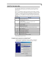
Страница 21: ...er is off and restored at power up Command Meaning DC n Show set decimation count Data logging rate in seconds L Start data logging Log data at the interval set by the decimation count DC 1 sets a one second interval L Stop data logging P Enable front panel control P Disable front panel control Prevent set point from being changed with panel controls SC Show coeffecients TE Read environment temper...

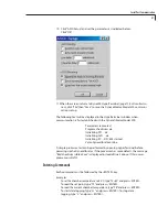
Страница 22: ...essary The following screen will appear 3 Click OK which reveals the next screen 4 Enter a name such as dyna500 and select an icon to associate with the file Then click OK 5 If necessary click through the warning screens again to get to this screen Serial Port Communication ...

Страница 23: ...ropriate COM port and click OK to bring up this screen 7 Set the port parameters as indicated above and click OK 8 Now we are at the dyna500 HyperTerminal screen below Select File then Properties Serial Port Communication ...

Страница 24: ...20 9 On the dyna500 Properties screen above click Settings to bring up the screen below Click Settings Click ASCII Setup Serial Port Communication ...

Страница 25: ...lizing IIC DS1624 started Valco Dynacalibrator online A simple processor test can be performed by opening HyperTerminal before powering up the Dynacalibrator If the processor has some defects the message Bad checksum in Block xxx is displayed instead of line 2 above If this occurs please consult VICI Entering Commands Each command must be followed by the ENTER key Examples To set the chamber tempe...

Страница 26: ...ion flow control valves to the pre calculated span points making sure as always that the total calibrator output flow exceeds the suction rate total of the suction rates of the analyzer s being calibrated Align the cen ters of the floats in the flowmeters to the selected scale readings Allow the analyzer reading to stabilize at the zero point usually about ten minutes before calibrating or recordi...

Страница 27: ...in permeation devices in an appropriate manner as described in permeation device literature 5 Secure the chamber cap with the tool provided 6 Reinstall the front panel assembly and rotate the panel lock screw 90 clockwise 7 Place devices in the containers provided and store them in an appropriate place until further use is required A refrigerator or freezer is recommended 8 Allow the carrier flow ...

Страница 28: ...lution stream flow rate 2 the permeation chamber temperature or 3 the number and or type of permeation devices The fastest simplest and most common method is to change only the dilution flow rate The carrier flows at a fixed rate maintained at a constant value by a sapphire orifice plate and a differential pressure regulator Orifice sizes are available for rates of 80 376 sccm The dilution flow is...

Страница 29: ... flow through the unit in relative terms Configuration 0 The plumbing configuration designated 0 Figure 6 consists of a single input port an integral micron filter pressure regulator assembly and a tee Dry gas air nitrogen etc at the appropriate pressure is supplied by the user to the supply inlet on the back panel Particulates larger than 30 microns are removed by filter F1 Line regulator PR1 is ...

Страница 30: ...eps the voltage down and regulates the output to 24 VDC If the cord end type is inappropriate for your locale please contact Vici Metronics for a replacement cord The main power switch S1 is on the front panel along with the main fuse F1 When the main power switch is on 24 VDC energizes the main power indicator on the front panel as well as the fan and stream switching solenoids Power to the perme...

Страница 31: ...0 hours Instrument Inspection and Cleaning The following procedure should be performed quarterly for units in continuous service or at least after every 1000 hours of service For the steps which call for disassembly see the appropriate paragraph in this section 1 Remove the unit from service according to the shut down procedures on page 26 Disconnect all power and plumbing 2 Remove the top cover o...

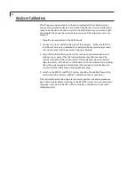
Страница 32: ...d for flow verification To verify the flow rate a one liter N I S T traceable flowmeter is recommended After using the appropriate leak checking proce dures to determine that the calibrator has no leaks proceed as follows 1 Remove power from the unit 2 Remove the top cover of the unit by unscrewing the six allen screws on each side of the instrument above the side bars 3 Close the dilution flow co...

Страница 33: ...aracterization is then modeled and corrections are calculated based on the model response The corrections are input and then the multiple setpoints are again run with the PRT and must fall within the specification in order to move to final assembly To define this process further is outside of the scope of this document and the range of work that is done by field services Calibration temperatures a...

Страница 34: ...tages The first method using leak detection fluid Leak Tek Snoop soap solution etc is relatively fast but is somewhat messy and requires careful cleanup after the leak is located and repaired The second method isolating components by breaking connections can consume more time but does not require cleanup Leak Detection Fluid Method 1 Remove the top cover of the unit by unscrewing the six allen scr...

Страница 35: ...nches of water 3 Starting at the air source end of the suspect loop break a fitting and using an appropriate adapter connect the leak checker gauge to the upstream side of the dis connected joint 4 Open the valve on the air source and slowly charge the unit until the gauge reads 20 inches of water Close the valve on the air source 5 Monitor the gauge for at least 30 seconds If the reading does not...

Страница 36: ...32 Model Number Breakdown ...

Страница 37: ...rom or relating in any manner to these goods This Limited Warranty does not cover lamps or fuses damage due to improper shipping damage due to improper use damage due to modifications or alterations damage due to improper maintenance This Limited Warranty does not cover defects damage or nonconformity result ing from abuse misuse neglect lack of reasonable care modification or the attachment of im...

Отзывы: