


Chapter 4 ________________________________________________________________ Operation
VAISALA _______________________________________________________________________ 67
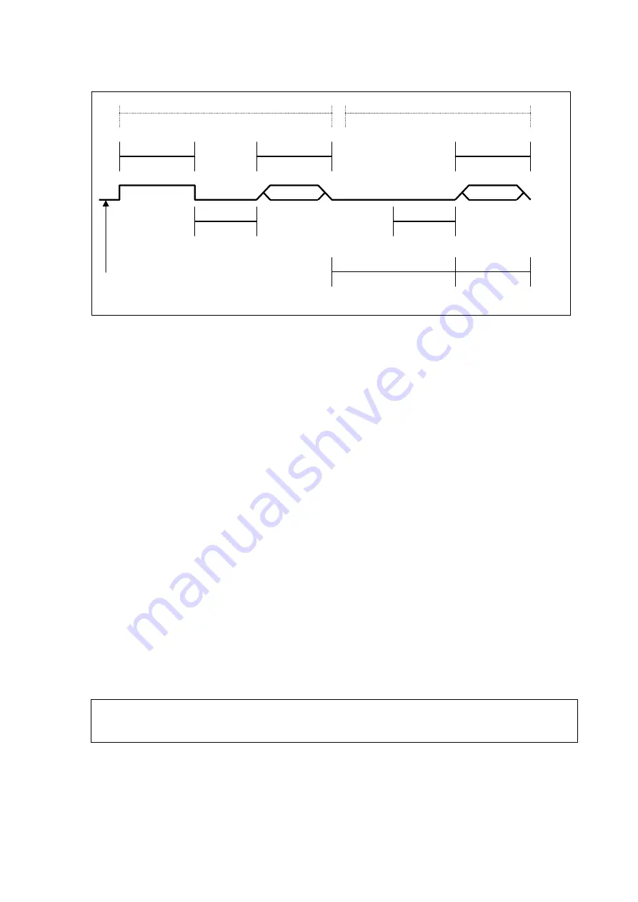
Figure 12
Timing Diagram
- After receiving the break and the command, the addressed sensor sets
the data line to marking at 8.33 milliseconds and then send the
response. (Tolerance: -0.40 milliseconds.) The start bit of the first
response byte must start within 15 milliseconds after the stop bit of the
last byte of the command. (Tolerance: +0.40 milliseconds.)
- After a sensor transmits the last character of a response, it must
relinquish control of the data line within 7.5 milliseconds. (Tolerance:
+0.40 milliseconds.)
- No more than 1.66 milliseconds of marking are allowed between the
end of the stop bit and the start bit (e.g., between characters) on any
characters in the command or the response. (No tolerance.) This
permits a response to an M command to be sent within a
380-millisecond window.
- Sensors must return to a low-power standby mode after receiving an
invalid address or after detecting a marking state on the data line for
100 milliseconds. (Tolerance: +0.40 milliseconds.)
- When a recorder addresses a different sensor, or if the data line has
been in the marking state for more than 87 milliseconds, the next
command must be preceded by a break.
NOTE
In addition to being a power consumption state, the low power standby
mode is a protocol state and a break is required to leave that state.
DATA
SENSOR
break
(at least 12
milliseconds)
command
response
SDI-12
Data Line
marking
(at least 8.33
milliseconds)
marking
(at least 8.33
milliseconds)
maximum time
380 ms most commands
780ms D0,R0 commands
sensor must respond
within 15


