*****INTERNAL*****30 R_D proof- 26.10.2022 / 09:15:46- VaillantGroup\DOC-agt\Brand\VIH_QW_190_6\ENG\OI-II_GB_0020291525
8
Operating instructions 0020291525_04
Button
Meaning
or
–
Navigating between individual menu items
–
Increasing or decreasing the chosen set
value
Adjustable values flash in the display.
You must always confirm a change to a value. Only then is
the new setting saved. You can press
to cancel a pro-
cess at any time. If you do not press any buttons for longer
than 15 minutes, the display returns to the basic display.
3.8
Type designation and serial number
The type designation and serial number are on the data
plate.
3.9
CE marking
The CE marking shows that the products comply with the
basic requirements of the applicable directives as stated on
the declaration of conformity.
The declaration of conformity can be viewed at the manufac-
turer's site.
3.10
Benchmark
Vaillant is a licensed member of the Benchmark Scheme
which aims to improve the standards of installation and com-
missioning of domestic heating and hot water systems in the
UK and to encourage regular servicing to optimise safety, ef-
ficiency and performance.
Benchmark is managed and promoted by the Heating
and Hotwater Industry Council. For more information visit
www.benchmark.org.uk.
▶
Please ensure that the installer has fully completed the
Benchmark Checklist on the inside back pages of the
installation instructions supplied with the product and
that you have signed it to say that you have received a
full and clear explanation of its operation. The installer is
legally required to complete a commissioning checklist
as a means of complying with the appropriate Building
Regulations (England and Wales).
All installations must be notified to Local Area Building Con-
trol either directly or through a Competent Persons Scheme.
A Building Regulations Compliance Certificate will then be is-
sued to the customer who should, on receipt, write the Noti-
fication Number on the Benchmark Checklist.
This product should be serviced regularly to optimise its
safety, efficiency and performance. The service engineer
should complete the relevant Service Record on the Bench-
mark Checklist after each service.
The Benchmark Checklist will be required in the event of any
warranty.
3.11
Safety devices
3.11.1 Frost protection function
The frost protection function for the system is controlled us-
ing the product itself or using the optional system control. If
the system control fails, the product guarantees limited frost
protection for the heating circuit.
At negative outdoor temperatures, there is an increased risk
of the heating water freezing if a heat pump fault occurs, e.g.
due to a power cut or a defective compressor.
3.11.2 Low-water pressure protection
This function continuously monitors the heating water pres-
sure in order to prevent a possible loss of heating water.
3.11.3 Freeze protection
This function prevents the unit's internal heating circuit from
freezing when the heating flow temperature drops below a
certain value.
If the heating flow temperature of the outdoor unit falls below
4 °C, the compressor is switched on in order to increase the
heating flow temperature.
3.11.4 Pump blocking protection
This function prevents the pumps for heating water from
sticking. The pumps, which were out of operation for
23 hours, are switched on for 10
–
20 seconds, one after the
other.
3.11.5 Safety cut-out (SCO) in the heating circuit
If the temperature in the heating circuit of the internal elec-
tric back-up heater exceeds the maximum temperature, the
safety cut-out shuts down the electric back-up heater as a
securing measure. After it is triggered, the safety cut-out
must be replaced.
–
Max. heating circuit temperature: 89
℃
4
Operation
4.1
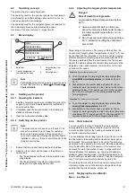
Basic display
120
kWh/d
E
1
The displays shows the basic display with the current status
of the product. The daily energy yield
(1)
is displayed in the
centre of the display.
If you press a selection button, the activated function is dis-
played in the display.
As soon as a fault message is present, the basic displays
switches to the fault message.
Содержание uniTOWER plus
Страница 2: ...2 en Operating instructions 3 en Installation and maintenance instructions 15...
Страница 71: ......


