6 Start-up
20
Installation instructions aroTHERM 0020217827_03
In various operating modes, the noises come from the heat
pump (Start, Thawing, Stop).
6.12
Adjusting the heating circuit
6.12.1 Purge the heating circuit
1.
Connect one end of the hose to the purging valve.
2.
In order to collect the residual glycol when purging the
heating circuit, insert the other end of the hose into the
mixing container.
3.
Close the isolation valves on the back of the product.
4.
Increase the pressure in the heating circuit.
5.
Open the purging valve with an open-ended spanner.
–
Working materials: SW10 open-end spanner
6.
Open the lower isolation valve on the back of the
product.
7.
If liquid escapes from the pipe, close the purging valve.
8.
Repeat the work steps for all hydraulic circuits by chan-
ging the direction of the 3-port diverter valve.
9.
Check the pressure in the heating circuit. If necessary,
increase it.
–
Operating pressure: 0.15 to 0.2 MPa (1.50 to
2.0 bar)
10. Open the service valves on the back of the product.
11. Remove the hose and the mixing container.
Note
The system control has a purging function.
The purging function can be started via the
heat pump control interface module. Within
15 minutes, the pumps are switched on for a
period of 30 seconds and switched off again
(30 seconds).
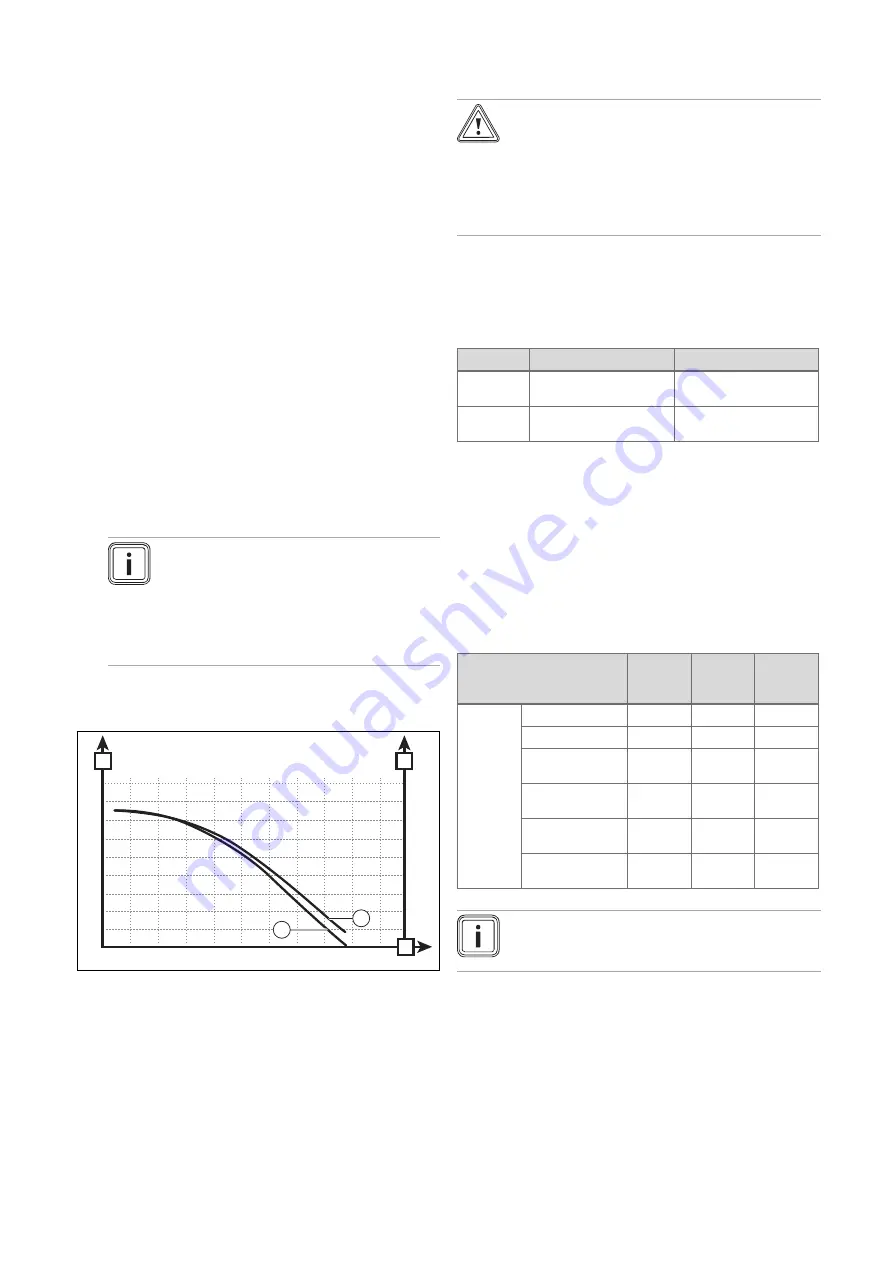
6.12.1.1 Available pressure in the heat pump heating
circuit
A
B
0
10
20
30
40
50
60
70
80
500
0
1000
1500
2000
C
100
200
300
400
500
600
700
800
90
900
2500
2
1
1
VWL 55/3 A 230 V
(water temperature 20
°C)
2
VWL 85/3 A 230 V
(water temperature 20
°C)
A
Remaining feed head
(kPa)
B
Flow rate (l/h)
C
Remaining feed head
[mbar]
6.12.2 Adjusting the heating circuit flow rate
Caution.
Risk of material damage due to frost
If the minimum flow rate is too low, the heat
exchanger may become damaged by frost.
▶
Operate the product with a sufficient flow
rate (see table).
The product is designed for operation between the minimum
flow rate and maximum flow rate, as specified in the table. If
the product is operated with the minimum flow rate, this res-
ults in a loss of energy and efficiency. The heating comfort is
still guaranteed but the energy savings are reduced.
VWL 55/3
VWL 85/3
Minimum
flow rate
380 l/h
380 l/h
Maximum
flow rate
860 l/h
1,400 l/h
You can read the flow rate directly from the controller. De-
pending on the type of liquid in the heating circuit, the flow
rate displayed on the controller may be exaggerated.
Example: If you use a 30% mixture of propylene glycol and
the liquid temperature is 5 °C, you must subtract 400 l/h from
the value shown on the display.
▶
Use the following table to compare the various exaggera-
tion flow rate values depending on liquid type.
–
Applies for: VWL 55/3 A 230 V,
VWL 85/3 A 230 V
Flow rate increase (l/h)
Temper-
ature
5 °C
Temper-
ature
15 °C
Temper-
ature
25 °C
Liquid
type
Water
0
0
0
60% alcohol
0
0
0
30% propylene
glycol
400
240
120
50% propylene
glycol
650
500
400
30% ethylene
glycol
120
0
0
50% ethylene
glycol
400
140
50
Note
Insufficient purging may lead to deviations in the
flow rate.
▶
If you cannot reach the minimum flow rate, install an ad-
ditional pump.
▶
If you cannot reach the recommended flow rate, adjust
the heating circuit pressure on the controller and, if ne-
cessary, use a bypass valve (item 50).
6.12.3 Adapting the unit to the heating installation
The installation assistant is launched when the product is
switched on for the first time.
If you have already filled the heating installation and termin-
ated the installation assistant, but want to set the most im-
Содержание aroTHERM VWL 55/3 A 230 V
Страница 39: ......


