LAYOUT AND FUNCTION
18
4
LAYOUT AND FUNCTION
4.1
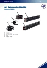
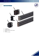
System description VCL2/VCL3
The compact wiper line VCL was developed especially for various applications in intralogistics. With its com-
pact dimensions and durability, the VCL possesses the ideal properties for potential shuttle applications in au-
tomated small parts stores or for other transfer carriages. Additional features are short installation times due
to the small number of different components (–50%) and the robust clip fastening system.
The VCL comes in two- or multiple-pin versions.
Safety
The compact wiper line has been designed according to VDE 0100. It meets today’s requirements on the safety
of a conductor system and is contact-protected in acc. with VDE 0470, Part 1 (protection class IP 2X). The cur-
rent collectors are protected against contact only if the carbon brushes are fully located in the conductor rails.
For conductor rail systems located at arm's length, where under normal operation the current collectors leave
the conductor rails, contact protection must be provided on site, e.g. by means of barriers or by switching off.
This, however, only applies to voltages above 25 volts AC or 60 volts DC.
The VDE finger shows that it cannot touch live parts. The insulation rail covering the conductor rail offers good
insulation for maximum safety. Several wiper lines can be combined with one another. Only little space is re-
quired.
Application
Only for indoor systems with travel speeds of up to 300 m/min.
Hangers
The maximum distance between the hangers is 0.8 m.
Connectors
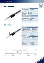
Joint connectors are used for the electrical and mechanical connection of the conductor rail sections. Every
connection point is protected against contact with a cover cap.
Linear expansions
• The conductor rails are permanently connected to each other by means of conductor rail connectors to
form a continuous conductor profile. The connecting caps are clamped between the two connected con-
ductor rails and travel along with the conductor rail joint.
• To compensate for changes in length, the insulation profile is 7.5 mm shorter for end segments and 15
mm shorter for the conductor system itself. The transfer guide also serves as an end cap, feed terminal
and fixpoint. Generally, the feed terminal is also the fixpoint and the end cap is the moving part.
• Expansion sections are required in special cases only. For instance to compensate for a structural expan-
sion joint in the building, for system lengths exceeding 150 m, or for fixpoints on both ends of the system.
Содержание VCL Series
Страница 95: ...INDEX 93 U Unloading 88...
Страница 96: ...CE Technical Documentation...


