background image

page 68 of 80

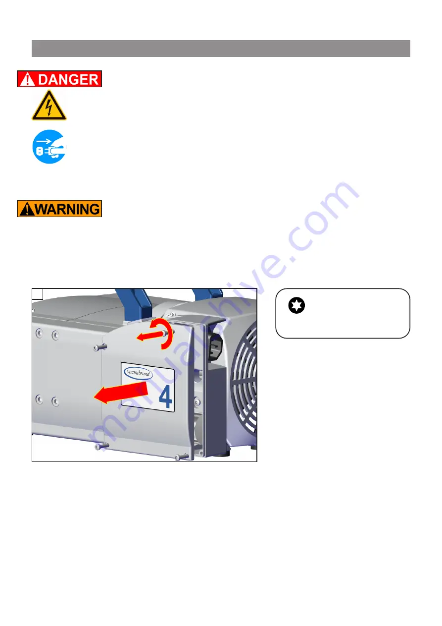
 Replacing the fuse

 Danger due to electrical voltage.


Switch off the pump. 

 Disconnect the electrical power cord

 before open-

ing the terminal box. After disconnecting from power, 

wait five seconds

 to allow the capacitors to discharge. 

+

 The replacing of the fuse has to be carried out by a 

trained electrician.

After replacing the fuse, the pump must be checked for 

electric safety (see below)! Identify and eliminate the 

cause of failure before switching on the pump again.

1

T20

4x

Содержание MZ 2C NT+2AK

Страница 1: ...Instructions for use Technology for Vacuum Systems ME 2C NT ME 4C NT ME 4C NT 2 AK ME 8C NT ME 8C NT 2 AK MZ 2C NT MZ 2C NT 2 AK MZ 2C NT AK M D MZ 2C NT AK EK MZ 2C NT AK Synchro EK MD 4C NT MD 4C NT...

Страница 2: ...ed intensively including an endurance run of 14 hours Any faults even those which oc cur rarely are identified and can be eliminated immediately After completion of the endurance run every pump is tes...

Страница 3: ...equired measures must be applied Safety instructions for vacuum equipment FR Attention Le mode d emploi pr sent n est pas disponible dans toutes les langues d Union Europ enne L utilisateur ne doit me...

Страница 4: ...tiende este manual En este caso se debe disponer de una traducci n t cnicamente correcta del manual completo El manual debe ser le do y entendido completamente y deben aplicarse todas las medidas de s...

Страница 5: ...nte letto e compreso prima di operare con lo strumento e devono essere applicati tutti gli accorgimenti richiesti Istruzioni di sicurezza per apparecchi a vuoto JP KR LT D mesio is vadovas n ra pateik...

Страница 6: ...o ci przeczytana i zrozumiana przed podj ciem pracy z urz dzeniem oraz nale y podj wszystkie niezb dne kroki zwi zane z prawid owym uzytkowaniem Wskaz wki bezpiecze stwa do urz dze pr niowych PT Aten...

Страница 7: ...opravljene pa moraja biti tudi vse potrebne meritve Varnostni nasveti za vakuumske naprave SK Upozornenie Tento manu l nie je k dispoz cii vo v etk ch jazykoch E U vate nesmie obsluhova zariadenie pok...

Страница 8: ...res 27 Wetted parts 30 Abbreviations 31 Pump parts 31 Use and operation 40 Installing a pump in a vacuum system 40 During operation 44 Important notes regarding the use of gas ballast 46 Important not...

Страница 9: ...om the pump and the pumped substances VACUUBRAND disclaims any liability for inappropri ate use of these pumps and for damage from failure to follow instructions contained in this manual This manual i...

Страница 10: ...Electronic components must not be disposed of in the domestic waste at the end of their service life Used electronic devices contain harmful substances that can cause damage to the environment or huma...

Страница 11: ...will void any and all warranty claims for those deficiencies Replace the protective caps if the equipment is not used immediately Store the equipment in dry and non corrosive conditions see also Techn...

Страница 12: ...environmental and oper ating conditions Operation despite obvious errors or defective safety devices Unauthorized extensions conversions or repairs in particular when these impair safety The use of un...

Страница 13: ...he pump in a cabinet or a housing Make sure ventilation is adequate to maintain recom mended operating temperature Install an external au tomatic ventilation system if necessary If pumping hot process...

Страница 14: ...outlet Do not permit any uncontrolled pressurizing Check the overpressure safety relief device at the ex haust waste vapor condenser at appropriate intervals Keep the electrical power cord away from...

Страница 15: ...et pipe is always free and that it cannot get blocked If installing an optional cool ant valve it must always be in the supply line of the exhaust waste vapor condenser Make sure ventilation is adequa...

Страница 16: ...Do not use this product in an area where it can fall or be pulled into water or other liquids This product may only be used indoors in a non explo sive atmosphere and in a dry environment Adopt suita...

Страница 17: ...ee section Important information Equipment marking ATEX pg 24 The pumps are not suitable to pump any of the sub stances listed below Do not pump unstable substances substances which react explosively...

Страница 18: ...the pumped substances with each other and with the pump s materials Safety during operation Adopt suitable measures to prevent the release of dan gerous toxic explosive corrosive noxious or pollut in...

Страница 19: ...ety goggles Interruption of the pump e g due to power failure failure of connected components or of parts of the sup ply or change in parameters must not be allowed to lead to dangerous conditions In...

Страница 20: ...ated in case of permanent high gas flow The temperatures that are produced during operation may cause burns Avoid direct contact with the surface Provide a suitable contact guard if necessary Ensure t...

Страница 21: ...s see section Repair Maintenance Return Calibration pg 70 are followed Take advantage of our service seminars which put special focus on the maintenance and repair of vacuum pumps For details and for...

Страница 22: ...tor capacitor fails the capaci tor may get hot It may even melt or emit a flame which could be dangerous for persons and equipment in the vicinity The capacitors have to be replaced by an electrician...

Страница 23: ...page 23 of 80 Ensure that the maintenance technician is familiar with the safety procedures which relate to the products processed by the pumping system Only dismantle the pump as far as necessary...

Страница 24: ...ed by gases vapors or mists normally don t occur or if they do occur are likely to do so only infrequently and for a short period only Equipment in this category ensures the requisite level of protect...

Страница 25: ...s or Techni cal data After any intervention at the equipment e g repair maintenance the ul timate vacuum of the pump has to be checked Only if the pump achieves its specified ultimate vacuum is the pu...

Страница 26: ...ion altitude above mean sea level ft m 6500 2000 No load speed 50 60 Hz rpm 1500 1800 Device fuse slow blow fuse 6 3 A Motor protection thermal cutout manual reset Overvoltage category II Degree of pr...

Страница 27: ...r tubing I D 3 8 or small flange KF 16 hose nozzle DN 10 mm or small flange KF 16 Outlet hose nozzle for tubing I D 3 8 hose nozzle DN 10 mm Dimensions L x W x H approx design 2 AK in mm in mm 9 6 x 8...

Страница 28: ...V 50 60 Hz 120 V 60 Hz 200 230 V 50 60 Hz 230 V 50 60 Hz A A A 3 4 1 8 1 8 Inlet hose nozzle for tubing I D 3 8 or small flange KF 16 hose nozzle DN 10 mm or small flange KF 16 Outlet hose nozzle for...

Страница 29: ...20 V 60 Hz Dual voltage motor 230 V 50 60 Hz 100 115 V 50 60 Hz 120 V 60 Hz 200 230 V 50 60 Hz Maximum rated cur rent at 100 V 50 60 Hz 120 V 60 Hz 100 115 V 50 60 Hz 120V 60 Hz 200 230 V 50 60 Hz 230...

Страница 30: ...systems waste vapor condenser Vacuum systems 2 AK PTFE carbon reinforced PET PP Tubing PTFE Flow control diaphragm PTFE Valve block SYNCHRO design PP Valves valve block SYNCHRO FFKM Distribution head...

Страница 31: ...lve block 17 Distribution head 18 Blind plug 19 Voltage selection switch 20 Pump support We reserve the right for technical modification without prior notice Pump parts Abbreviations ETFE Ethylene Tet...

Страница 32: ...page 32 of 80 ME 4C NT 1 5 4 7 6 8 2 ME 2C NT 1 5 4 7 6 8 2...

Страница 33: ...page 33 of 80 1 5 3 4 7 6 2 8 1 3 MZ 2C NT KF 16 MZ 2C NT ME 4C NT 2 AK Power connection see ME 4C NT 6 1 2 7 9 18 17 4 19 20...

Страница 34: ...page 34 of 80 ME 8C NT MD 4C NT 1 5 3 4 7 6 2 8 8 5 4 7 6 1 2...

Страница 35: ...NT 2 AK 6 1 2 3 7 9 18 17 Power connection and ON OFF switch see MZ 2C NT 20 MZ 2C NT AK EK 6 1 2 18 7 10 11 12 13 9 17 alternately small flange KF DN 16 at the inlet 20 Power connection and ON OFF s...

Страница 36: ...e 36 of 80 MZ 2C NT AK SYNCHRO EK 6 1 3 7 10 11 9 14 2 12 13 16 20 Power connection and ON OFF switch see MZ 2C NT MZ 2C NT AK M D 6 1 2 3 7 9 15 14 17 20 Power connection and ON OFF switch see MZ 2C...

Страница 37: ...page 37 of 80 PC 101 NT 6 1 3 7 10 11 9 14 15 2 12 13 17 Power connection and ON OFF switch see MZ 2C NT 20 6 1 2 7 9 18 17 ME 8C NT 2 AK Power connection and ON OFF switch see ME 8C NT 20...

Страница 38: ...page 38 of 80 MD 4C NT AK EK 6 1 7 10 11 9 2 12 13 18 17 3 20 Power connection and ON OFF switch see MD 4C NT MD 4C NT 2 AK 6 1 2 3 7 9 18 17 20 Power connection and ON OFF switch see MD 4C NT...

Страница 39: ...9 of 80 MD 4C NT AK SYNCHRO EK 14 1 7 6 9 11 2 12 13 3 10 16 20 Power connection and ON OFF switch see MD 4C NT PC 201 NT 6 1 7 10 11 9 14 15 2 12 13 3 17 20 Power connection and ON OFF switch see MD...

Страница 40: ...te filters You must ensure their suitability concerning gas flow chemical resistance and resistance to clogging prior to use Make sure ventilation is adequate especially if the pump is installed in an...

Страница 41: ...ng from the pump or provide other measures to avoid backflow of condensate towards the pump NOTICE Voltage selection switch 1 Disconnect the electrical power cord 2 Use a screw driver to adjust the vo...

Страница 42: ...e with union nut Take the hose nozzle with attached compression fer rule and union nut out of the catchpot and put onto in let connection version 2 AK onto inlet and outlet con nections Tighten the un...

Страница 43: ...see image at the waste vapor condenser Check all hose connections prior to starting operation of the cooling system Secure coolant hoses at the hose nozzles e g with hose clamps to prevent their acci...

Страница 44: ...p appropriately Due to the high compression ratio the pump might generate overpressure at the outlet Check pressure compatibility with system components e g exhaust tubing or exhaust valve at the outl...

Страница 45: ...pressure or pumping dusty gases for a long time may cause clogging of the silencer Check the silencer regularly and replace if necessary In case of overload the motor is shut down by a self hold therm...

Страница 46: ...s bal last Gas ballast is a continuous purge to keep the pump s in terior as clean as possible and to reduce the possibility of condensation inside the pump Oxygen enters the pump if using air as gas...

Страница 47: ...ap 180 In case of low boiling solvents when the formation of condensate is unlikely the use of gas ballast might be unnecessary Operating the pump without gas ballast in creases the solvent recovery r...

Страница 48: ...tempera tures that are produced during operation may cause burns Allow the equipment to cool before you drain the catchpot at the exhaust waste vapor condenser Use your personal protection equipment...

Страница 49: ...if possible purify if contaminated Shutdown storage The pump can be switched off under vacuum Short term Has the pump been exposed to condensate Allow the pump to continue to run at atmospheric pres...

Страница 50: ...ock SYNCHRO Seal ring for small flange KF DN 16 20662593 23120565 Hose nozzle for tubing I D 1 4 3 8 DN 6 10 mm 20642470 for inlet at valve block SYNCHRO Modification kit for small flange KF DN 16 206...

Страница 51: ...g 20638434 T piece for PTFE tubing 20638435 PTFE tubing sold by meter 20638644 For additional accessories such as vacuum valves small flange components vac uum gauges or vacuum controllers refer to ww...

Страница 52: ...l pumping speed Centring ring at small flange connection not correctly positioned or leak in the pipeline or vacuum system Check pump directly connect vacuum gauge directly at pump inlet then check co...

Страница 53: ...ssure especially with condensable vapors Diaphragm crack or diaphragm clamping disc loose Perform maintenance Other than above men tioned causes Contact local distributor Pump seized Contact local dis...

Страница 54: ...ance Avoid the release of pollutants Never operate a defective or damaged pump Take adequate precautions to protect people from the effects of dangerous substances that may have con taminated the pump...

Страница 55: ...the pump interior the diaphragms and the valves must be cleaned and the diaphragms and valves must be checked for cracks or other damage All bearings are encapsulated and are filled with long life lu...

Страница 56: ...not be disassembled The head covers can be removed along with the as sembled valve heads and fittings Service only one side of the pump at a time to avoid the mixing of parts Cleaning and inspecting...

Страница 57: ...page 57 of 80 Fittings and tubing of the different pump models ME 4C NT MZ 2C NT ME 8C NT MD 4C NT...

Страница 58: ...page 58 of 80 MZ 2C NT 2AK MZ 2C NT AK EK MZ 2C NT AK SYNCHRO EK PC 101 NT MD 4C NT 2AK MD 4C NT AK EK MD 4C NT AK SYNCHRO EK PC 201 NT ME 8C NT 2 AK...

Страница 59: ...ing disc with square head screw H Allen screw I Cap J Head cover K Square nut View of the disassembled pump head parts fig MD 4C NT L Fillister head screw M O ring N Valve O Valve head P Hose nozzle Q...

Страница 60: ...d O Open the hose clip U with a slotted screw driver Pull the tubing off the hose connector Disassemble head covers J to check the diaphragm F Unscrew four pump with one two heads or eight pump with f...

Страница 61: ...B Do not mix the washers from the different pump heads since these are set at the factory to ensure proper pump per formance Make sure that the original number is reassembled at the individual pump he...

Страница 62: ...mm wide Note Never use the diaphragm key with any additional tools like tongs or Allen keys without appropriate torque limitation Loosen the clamping brackets S on the valve heads O Unscrew at each c...

Страница 63: ...ves N See fig ure for the correct position of the valves Inlet side IN Marked IN next to the valve seat The valve tongue points at the kidney shaped orifice in the valve seat Outlet side EX Marked wit...

Страница 64: ...attention to the correct orientation of the head covers Housing with head alignment pin The head alignment pin A at the pump housing C has to fit into the recess at the head cover J Housing with mark...

Страница 65: ...with a Torx driver T20 Close the hinged covers Affix the connection tube V to the other side of the pump at the valve head O Pump on pump support Affix the connection tube V to the other side of the...

Страница 66: ...ecified ultimate vacuum is not achieved and if this does not change after the break in period Check hose connectors at pump heads for leaks If necessary recheck valve seats and pump chambers Checking...

Страница 67: ...ll the new one Check for correct position of the PTFE foil under the pressure relief valve Feed the PTFE hose into the inlet of the exhaust vapor condenser Mount the con denser with the counter holder...

Страница 68: ...e terminal box After disconnecting from power wait five seconds to allow the capacitors to discharge The replacing of the fuse has to be carried out by a trained electrician After replacing the fuse t...

Страница 69: ...2 1 2 2 2 20636542 Important Check operability and safety of the pump after repair and after replacing the device fuse Check the electrical safety protective conductor resis tance insulating resistan...

Страница 70: ...ed Also decontaminated devices must not returned to VACUUBRAND due to a residual risk The same conditions apply to on site work No repair maintenance return or calibration is possi ble unless the corr...

Страница 71: ...e parts for cosmetic reasons at your request and at your expense Before returning the device Pack the device properly if necessary please order origi nal packaging materials at your costs Mark the pac...

Страница 72: ...rmal wear and tear of wearing parts such as diaphragms seals valves vanes condensers oil and the breakage of glass or ceramic parts for the consequences of chemical electrochemical or electrical influ...

Страница 73: ...page 73 of 80 Declarations and certificates...

Страница 74: ...page 74 of 80...

Страница 75: ...page 75 of 80 This certificate is only valid for pumps with the respec tive mark Licensed Test mark on the pump rating plate...

Страница 76: ...se Period EFUP EFUP defines the period in years during which the hazardous substances contained in electrical and electronic products will not leak or mutate under normal operating conditions During n...

Страница 77: ...the above table the subassemblies are not intentionally manufactured or formulated with lead Pb mercury Hg cadmium Cd hexavalent chromium Cr VI polybrominated biphenyls PBB and polybrominated dipheny...

Страница 78: ...page 78 of 80...

Страница 79: ...page 79 of 80...

Страница 80: ...7 Wertheim GERMANY GERMANY Phone Head office 49 9342 808 0 Sales 49 9342 808 5550 Service 49 9342 808 5660 Fax 49 9342 808 5555 Email info vacuubrand com Web www vacuubrand com Version 20901002_EN_MZ2...

Отзывы: