background image


Fault codes and software

24h on-call service phone: +358 (0)40 83 71 150

32

4

navigation. When pressing again the arrow left over 5 s, the active control place 
jumps back to I/O or Fieldbus.

10. 3. 2. 11.  NXS00001V170

Replaced version: NXS00001V169.VCN

System software version: 11.73.8480

Changes in applications:

All applications made with new project tool NC1131-3.

When motor identification-run was done by using PC control, the drive did not 
accept new start command from PC until stop command was send even that drive 
was automatically already stopped after id-run sequency.

Help text is added for status word-signal when monitoring with NCDrive. 

Local/Remote Control application: All 3 pcs. Pt100 temperature values from Pt100 
option board (B8) are separately displayed on monitoring page (V1.21.8, 1.21.9 
and 1.21.10). ID numbers are given for them as well (ID50, 51 & 52) i.e tempera-
tures can be read for example via Profibus. 

Multi purpose application: ID numbers are given also for counter calues to make 
possible reading and resetting via fieldbusses. PowerOnTimeTripcounter, PowerOn-
TripCounterUnit and ResetOnTimeTripCounter = ID10, 1050 & 1051. EnergyMeter, 
EnergyMeterFormat and EnergyMeterUnit = ID11, 80 &81. EnergyTripCounter, 
EnergyTripCounterUnit and ResetMWhTripCounter = ID12, 1052 & 1053. 

Multi purpose application: ID value added for active warning = ID74

10. 3. 2. 12.  NXS00001V171

Replaced version: NXS00001V170.VCN

System software version: 11.74.8486

Changes in system software:

Currentcutter functionality is changed in FR7 500V and FR8 500V drives. 

10. 3. 2. 13.  NXS00001V172

Replaced version: NXS00001V171.VCN

System software version: 11.75.8546

Changes in system software:

The card description for OPTICI (Ethernet option board) is changed to be able to do 
the IP addressing using keypad. The parameters are visible automatically in the 
Expander boards menu. 

Содержание NX

Страница 1: ...VACON NX SERVICE MANUAL Overview ...

Страница 2: ...harging the capacitors in stored units 14 2 8 3 Recharging individual capacitors that have been stored 14 2 8 4 DC link capacitor tests and replacement 15 2 8 4 1 Test 15 2 8 4 2 Replacement 15 3 SERVICE TOOLS 17 3 1 Information 17 3 2 NC Load 1 0 17 17 3 3 NC Drive 17 3 3 1 NC Drive 2 0 7 17 3 3 2 NC Drive 2 0 8 18 3 3 3 NC Drive 2 0 11 18 3 4 NC SERVICE 18 3 4 1 Software version 1 09 18 3 4 2 So...

Страница 3: ...XS00001V162 28 4 3 2 4 NXS00001V163 28 4 3 2 5 NXS00001V164 28 4 3 2 6 NXS00001V165 28 4 3 2 7 NXS00001V166 29 4 3 2 8 NXS00001V167 30 4 3 2 9 NXS00001V168 31 4 3 2 10 NXS00001V169 31 4 3 2 11 NXS00001V170 32 4 3 2 12 NXS00001V171 32 4 3 2 13 NXS00001V172 32 4 3 2 14 NXS00001V173 33 4 3 3 NXP software information 33 4 3 3 1 NXP00002V156 33 4 3 3 2 NXP00002V158 33 4 3 3 3 NXP00002V159 34 4 3 3 4 NX...

Страница 4: ...uipment VB300 and 3 BOXTEST 103 5 1 2 1 3 VB300 103 5 1 2 2 3 BOXTEST 104 5 1 3 Testing the Eprom by panel 104 5 1 4 Testing the Eprom by Device Properties program 105 5 2 NX option boards 105 5 2 1 Basic I O boards NX OPT A_ 106 5 2 2 I O Expander boards NX OPT B_ 108 5 2 3 Fieldbus boards NX OPT C_ 110 5 2 4 Adapter boards NX OPT D_ 111 6 START UP AFTER REPAIR 112 6 1 An external DC power withou...

Страница 5: ...02B Layout updated Changes to following chapters After market service information 2nd Service tools 3rd and faultcodes and software 4th SM00002C General update SM00002D Service manual ID code table update TABLE 2 NX drive component version history Name New part code Old part code Valid from Changes to previous NXS Control board VB00252O VB00252N Esti mated 26 9 05 Current limit to panel increased ...

Страница 6: ...Revision history email service vacon com Phone 358 0 201 212 575 Fax 358 0 204 335 091 7 1 ...

Страница 7: ... ID codes for Vacon NX Service manuals Product range Manual ID code NX Overview SM00002 NXL MF2 SM00003 NXL MF3 SM00004 NXL MF4 SM00005 NXL MF5 SM00006 NXL MF6 SM00007 NXS P FR4 SM00008 NXS P FR5 SM00009 NXS P FR6 500V SM000010 NXS P FR6 690V SM000011 NXS P FR7 SM000012 NXS P FR8 SM000013 NXS P FR9 SM000014 NXP FR10 SM000015 NXP FR11 SM000016 NXP FR12 SM000017 NXP FR13 SM000018 NXP FR14 SM000019 N...

Страница 8: ...AL INFORMATION FOR CERTAIN STEPS MIGHT ALSO EXIST IN APPENDIX MANUALS 8 3 Appendix manual information Separate appendix manuals contain the following chapters NXP CH62 SM00033 NXP CH63 SM00034 NXP CH64 SM00035 NXP CH72 SM00036 NXP CH74 SM00037 NX Maintenance JIG for FR11 SM00041 Vacon CX CXL M4 M10 SM00050 Vacon CX M11 M13 SM00051 Vacon CXS SM00052 TABLE 4 Chapter information in the overview manua...

Страница 9: ... TO USE THIS MATERIAL AND PERFORM ANY OF THE SERVICE ACTIONS MENTIONED THE PERSONNEL PRE FORMING LOCAL SERVICE WORK ON THE DRIVES MUST HAVE QUALIFICATIONS THAT ARE IN ACCORDANCE WITH THEIR NATIONAL LAW 8 4 2 Personal safety notice Mechanical surfaces which display a warning hot surface sticker must not be touched Make sure the working environment is safe and there is nothing that will cause any ri...

Страница 10: ... specifications must be followed The torque specifications for mounting the AC Drive and the torque specifications for the cable connections must be followed Only use spare parts that are supplied by Vacon Plc Every service location must carry all specialized Vacon AC Drive tools the correct measuring equipment all of the necessary adapters and load motors for testing pur poses along with the corr...

Страница 11: ...he world are a part of the Vacon global service network and the local Service Center must provide adequate measures to ensure customer satisfac tion Only spare parts which are specified and approved by Vacon Plc are to be used to replace defect parts Boards are to be repaired only at Vacon Plc Service actions defined in a released SBU Service Bulletin authorizes the repair or modification of the b...

Страница 12: ...operly The operation of the cooling fans and the cleanness of the heat sink should be checked once in a while Regular maintenance is recommended to ensure trouble free operation and long life of the drive The following things should at least be included in the regular maintenance program It is also recommended as a good service practise for follow up maintenance that the counter values dates and t...

Страница 13: ... input phases L1 L2 The DC voltage has to be adjusted up to the nominal DC voltage level of the unit 1 35 Un AC and has to be supplied for at least one hour If a DC voltage is not available and the unit has been stored much longer than one year de energized consult the manufacturer before connecting the power 8 8 3 Recharging individual capacitors that have been stored When using spare part capaci...

Страница 14: ...n different voltage potentials has occurred in the DC link 8 8 4 2 Replacement Replacement of the capacitors when there is a short circuit in the capacitor All capacitors which are inter connectioned in the same bank between DC and DC See Figure 2 All capacitors should be replaced when the drive has been used for the period of time specified in chapter Recommended maintenance when considering the ...

Страница 15: ...After market service information email service vacon com Tel 358 0 201 212 575 Fax 358 0 204 335 091 16 2 ...

Страница 16: ...se refer to Contents in the Help menu The Nice to know information is as follows When a problem with an eeprom on a control power or option board is suspected F40 or is displayed Obtain Info Info is located under the Drive menu A new window opens and the content can be copied to the clipboard with the Copy To Clipboard push button 9 3 NC Drive See complete list of release information for NCDrive o...

Страница 17: ...any application VCN file All firmware signals can still be monitored for debugging during the service BACNet fieldbus OPTCJ board is now supported 9 3 3 NC Drive 2 0 11 The latest version is available on Vacon extranet 9 4 NC SERVICE NC Service supports NXS and NXP testing but not NXL testing 9 4 1 Software version 1 09 Does not support the testing of NXL or NXP2 control board 9 4 2 Software versi...

Страница 18: ...vice 9 5 1 Version 2 0 2 The Brake chopper been added as default to the programming and there have been changes to the drive ratings in pull down menus 9 5 2 Version 2 0 3 Support for newer system software versions which require ExtraData 3 3 This is the default in easy mode User manual V1 3 included 9 5 3 Version 2 0 4 Updated user s manual and program Possible to rescale the window Previously in...

Страница 19: ...nstructions for respective frame size in its NX Appen dix Manual 10 2 Fault codes All fault codes are described in flow charts below with an explanations and with mea sures to be done in different cases for solving the problem 10 2 1 NXL information NXL fault history can contain up to 5 faults and the oldest fault will dissapear There is none of save operation to the monitoring values in the fault...

Страница 20: ...appears in the manual F8 S1 Driver fault MF2 MF3 MF4 Driver circuit fault signal Appears also with F1 and F2 F8 S2 Internal fault Modulator assert F8 S3 Failed data reading on the EEPROM No connec tion to the EEPROM F8 S4 Failed data in power section of the EEPROM F8 S5 Unknown power section Size grade index 0 F8 S6 VB number of power board is not acceptable Unit can not identify the frame of powe...

Страница 21: ...dog fault Reason software bug hardware failure software overload F25 S2 Watchdog shooting of modulator F25 S3 Watchdog NMI Activation of NMI interrupt F25 S4 Watchdog DBC Debug F25 S5 Watchdog singlestep Debug F25 S6 Watchdog AM Address match interrupt F25 S7 Watchdog break F25 S8 Watchdog overflow Overflow interrupt F25 S9 Watchdog UDI Undefined instruction interrupt F29 Thermistor fault F34 S1 I...

Страница 22: ...h Vacon standard software Instructions in Fault codes in NXL unit on page 21 covers fault codes in software versions until NXSV151 11 55 6639 and NXPV145 12 26 7284 Special software or application can have different features or fault codes 10 3 1 NXL software information Must use only Vacon blue or yellow cable with NXL drives when connected to PC 10 3 1 1 NXL00005V146 Hardware compatible with all...

Страница 23: ...n fixed 10 3 1 4 NXL00005V242 Equal to NXL00005V142 except for new loader inside VCN file which supports both NXL processor versions This version to be used if customer is requiring old system software version See service bulletin SBU00024 0524 for more information 10 3 1 5 NXL00005V249 Changes to temperature measurement 10 3 1 6 NXL00005V250 See additional info from NXL Product annoncement dated ...

Страница 24: ...z Motor over temperature protection improved Start up Wizard improved Changes Application New alternative for PID actual value P2 9 3 7 Al1 Al2 Start up Wizard improved Prohibit freguency group 2 5 made visible Improvement of 4mA reference fault supervision 10 3 1 9 NXL00005V253 Replaced version NXL00005V252 Used in production since 19 09 2006 Changes Application Start up Wizard improved default c...

Страница 25: ... normal operation by making a fly ing start Easy local control selection is added When button is pressed for 5s the unit switches over to panel control and keypad reference is displayed NOTE This mode does not support any panel navigation When pressing the again for 5s the active control panel jumps back to l O or fieldbus 10 3 1 11 NXL00005V255 Used in production since 22 05 2007 Changes Firmware...

Страница 26: ... from V1 10 Parameter file downloading improved stop function P2 1 12 was not copied always coasting 10 3 1 15 NXL00005V259 Used in production since 07 05 2008 Changes Firmware Changes to the fan speed control of MF6 drives TABLE 10 Compatible boards with NXL Boards Voltage VB00351L Control board VB00350L MF4 500V VB00357G MF5 500V VB00558F MF6 500V VB00352P MF2 400V VB00353P MF3 400V VB00354K MF2...

Страница 27: ... correct info about downloaded VCN packet when trying to communicate with unit having version 163 NXS software Communication possible after generating VCN file by using the function generate database 10 3 2 6 NXS00001V165 Replaced version NXS00001V163 VCN System software version 11 68 8069 Changes in system software Increased filtering time for calculated open loop motor power Changes to stall pro...

Страница 28: ...CDrive Drive Parameter Sets PFC application PI output is not freezed anymore when limit controllers current limit etc are active or unit is stopped PFC application Motor identification run added PFC application There was possible to happen overflow when analogue input was scaled to narrow area Corrected 10 3 2 7 NXS00001V166 Replaced version NXS00001V165 VCN System software version 11 69 8170 Chan...

Страница 29: ...tely nominal current IGBT s will conduct continuously causing overload Fixed F11 problem for 500Hz disabled at high frequencies Stall frequency enabled again and stall frequency gap brought back into F15 faulth anged Corrected 10 3 2 8 NXS00001V167 Replaced version NXS00001V166 VCN System software version 11 70 8248 Changes in system software Romania added into language packet East Europe Added ne...

Страница 30: ...ng on 10 3 2 10 NXS00001V169 Replaced version NXS00001V168 VCN System software version 11 72 8392 Changes in system software Sine filter parameter added into system menu S6 7 5 Default is Not conn and other alternative is Connected which should be used when sine filter is connected in series to the motor Parameter sets values of motor control stabilizers to corre spond better the motor circuit wit...

Страница 31: ...bers are given for them as well ID50 51 52 i e tempera tures can be read for example via Profibus Multi purpose application ID numbers are given also for counter calues to make possible reading and resetting via fieldbusses PowerOnTimeTripcounter PowerOn TripCounterUnit and ResetOnTimeTripCounter ID10 1050 1051 EnergyMeter EnergyMeterFormat and EnergyMeterUnit ID11 80 81 EnergyTripCounter EnergyTr...

Страница 32: ... software Bug in the fault logic corrected With software version NXS00001V172 there was a possibility with some fault codes that when the fault was activated the fault code was shifted in the fault registers so that the last active fault was in the active fault 2 register and the active fault 1 register was empty 10 3 3 NXP software information 10 3 3 1 NXP00002V156 Hardware compatible with VB0025...

Страница 33: ...0251G VB00561F or newer versions Known feature option board parameters are not shown on the display if the option board data is old EEPROM data is wrong Board data has to be updated 10 3 3 6 NXP00002V162 Hardware compatible with VB00251G VB00561F or newer versions Bug OPTA7 ENC2_TYPE parameter changes encoder 1 type parameters 10 3 3 7 NXP00002V163 Hardware compatible with VB00251G VB00561F or new...

Страница 34: ...plications All applications If one reset input was active the unit did not accept reset from other source For instance when I O terminal reset was high reset via Profibus was not possible Local Remote control When mode 0 was selected to Place A Start Stop logic P2 2 1 the Reverse input did not work Corrected Local Remote control Reading of analogue inputs did not work when corresponding input filt...

Страница 35: ...erload Fixed F11 problem for 500Hz disabled at high frequencies Stall frequency enabled again and stall frequency gap brought back into F15 fault Fixed feature when loading parameters stored in another application from panel When downloading parameters from panel and the parameter value is not within the allowed max min range of unit the parameter is set to default value 10 3 3 11 NXP00002V167 Rep...

Страница 36: ...m software version 12 48 9146 VB00251 System software version 22 21 9203 VB00561 VB00661 Changes in system software Romania added into language packet East Europe Added new language packet East Europe II including languages English German French and Turkish Decreased the gain value of overvoltage controller of unit sizes FR9 and bigger When function load parameters up to panel was used and unit ha...

Страница 37: ...g fre quency fold back in case of high heatsink temperature Note NCDrive will support Sine filter parameter starting from NCDrive version 2 0 11 Accuracy of S curves of ramps has been improved Support for OPT AK sin cos encoder board added Changes in applications Added new Start function alternative Conditional Flying start Parameter ID505 2 When function is activated the unit performs flying star...

Страница 38: ... ID11 80 81 EnergyTripCounter EnergyTripCounterUnit and ResetMWhTripCounter ID12 1052 1053 Multi purpose application ID value added for active warning ID74 Multi purpose application DC braking current setting switched back to default after power down Corrected Multi purpose application Identification run parameter 2 6 16 has 2 addtitional options Setting alternative 4 Ident all and other one is in...

Страница 39: ...eral applications without Vacon drive synch Improvements for NC Drive CAN communication during signal monitoring The ben efits can be seen with newer release than NCDrive 2 0 10 10 3 3 17 NXP00002V173 Replaced version NXP00002V172 VCN System software version 12 51 9476 VB00251 System software version 22 24 9542 VB00561 VB00661 Changes in system software Flying start function found not working with...

Страница 40: ...wing parameters have been added for the additional temperature measure ment channels P2 7 37 PT100 2 Numbers P2 7 38 PT100 2 Warning Limit P2 7 39 PT100 Fault Limit Temperatures of the second board can be read from the following monitor values V1 21 25 PT100 4 Temp V1 21 26 PT100 5 Temp V 1 21 27 PT100 6 Temp New option added for parameter P2 7 36 which defines Safe Disable mode The new option 0 W...

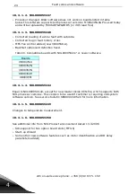
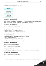
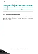
Страница 41: ...tely in fault situations Instructions how to test the control unit using NC Service is in another section Most of the procedures for the different fault codes only explain how to proceed with the power unit section AD BF CI AE CJ AF CL AK CM AL TABLE 15 I O monitoring support to NX option boards NXOPT A series NXOPT B series NXOPT C series NXOPT D series ...

Страница 42: ...Fault codes and software email service vacon com Tel 358 0 201 212 575 Fax 358 0 204 335 091 43 4 10 5 Fault codes 10 5 1 Fault code flowcharts ...

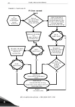
Страница 43: ...t again with checked corrected settings YES External fault Current cutter time too long Check motor motor cable motor load Install output filters Internal fault Check current measurement circuit NO Did F1 appear again Remove motor cables and power up drive to standby mode Measure all output phase currents and compare to monitoring page YES Was measurements same as displayed value NO YES Did F1 app...

Страница 44: ...deceleration time use of brake chopper etc Start again with checked corrected settings YES Did fault occur in standby mode NO NOTE Triplimits NX2 437V DC NX5 911V DC NX6 1200V DC Internal fault Check the voltage measurement circuit External fault Fault was generated for a reason Sudden changes in mains voltage voltage spikes in the mains temporary feature of load break resistor too small Did F2 oc...

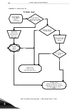
Страница 45: ...as running Did fault occur in standby mode NO External fault Software trigged the sum of motor phase current is not zero Damaged motor or motor cable NO Disconnect motor cable from drive and give start command YES YES Internal fault Check current measurement circuit Did F3 appear again YES Measure output currents in all phases Are all phases equal NO YES NO FIGURE 5 Fault code F3 ...

Страница 46: ... FR7 fault is not used Fr7 FR8 Power Card overtemperature will indicate F4 Fr10 Driver power too low will indicate F4 Service actions are based on unit size FR7 Fr7 Fr8 Fr10 Fault occurred due to interference because signal is not used Fault activated because power board is too hot or faulty powerboard Driver voltage is too low on the ASIC board FIGURE 6 Fault code F4 ...

Страница 47: ...g switch fault If fault Test the control board Did it pass the test Replace control board and load software intoit Remember parameter settings NO YES FR4 FR8 frequency converters FR9 FR13 frequency converters Possible fault in cable connection between control and power board Replace it No instructions available FIGURE 7 Fault code F5 ...

Страница 48: ...occur several times during normal operation External reason trigged the fault Check cable connections NO Test control unit YES Inernal interference trigged the fault Check connections between control board and I O boards Did it pass the test YES NOTE Fault is trigged from pin 6 in each I O slot Signal not used in standard I O boards Replace control board Load software and also parameter settings N...

Страница 49: ...t history Measure isolation resistance and resistance on the brake resistor Were measurements OK Fault caused by faulty brake resistor Change it NO Measure brake chopper Is brake chopper used YES NO Replace broken power module and power board Were all measurement s OK NO YES YES FR9 FR13 FR4 FR8 No instructions available Measure power module directly from its terminals Replace broken power module ...

Страница 50: ...eck logged data in fault history NOTE Subcode of the fault 1 Output phase control fault 2 uP watchdog without initialization 3 Vacon Bus watchdog problem 4 Software trigged application 5 Too much noise in Vacon Bus 6 Impossible to reset ASIC controller 7 ASIC controller does not close charge switch Proceed to prospect the reason of the fault code FIGURE 10 Fault code F8 ...

Страница 51: ...eration time use of brake chopper etc Start again with checked corrected settings YES Did fault occur in standby mode NO NOTE Triplimits NX2 183V DC NX5 333V DC NX6 460V DC Internal fault Check the voltage measurement circuit and capacitors External fault Fault was generated for a reason Sudden changes in mains voltage voltage dips in the mains temporary feature of load Did F9 occur again NO Measu...

Страница 52: ...res in the inverter F10 displayed Check logged data in fault history Measure mains voltage at mains terminals External reason activeted the fault Too low voltage for a longer time Check if fuses are blown Did you find blown fuses YES NO Root cause might be component failure or caused by voltage dips in the mains Were there broken parts Internal fault Check mains supervision NO Replace broken parts...

Страница 53: ...and motor OK YES F11 displayed Check logged data in fault history Measure motorcable connection and motor NOTE This fault may occur with small motor or without motor in drive with software versions older than NXS00001V104 11 19 4886 NXP00002V105 12 07 5100 F11 occurred due to an external fault NO Internal fault Check current measurement circuit ...

Страница 54: ...vision Are all measurements OK NO YES Is brakechopper maincircuit OK YES NO F12 displayed Check logged data in fault history Internal fault Replace brake chopper and power board Replace brake resistor and or cables FR4 FR8 FR9 FR13 Measure brakechopper maincircuit No instructions available Measure brake chopper gate circuit Is brake chopper gate circuit OK NO Internal fault Check correct cables be...

Страница 55: ...onitoring page F13 Undertemperature fault Did value correspond to ambient temperature and temperature lower than 10 C NO YES F13 displayed Check logged data in fault history External fault Temperature is too low Internal fault Check the temperature measurment circuit NOTE FR9 Power board has its own temperature measurement which can activate F13 ...

Страница 56: ...ta in fault history External fault Temperature is too high Internal fault Check the temperature measurment circuit NOTE FR9 Power board has its own temperature measurement which can activate F14 Check operation of the fan Did fan operate properly External fault Make sure that unit gets clean air Check condition of the cooling element NO YES Internal fault Check circuitry for the fan and the fan it...

Страница 57: ...l frequency Stall frequency gap Stall time Is motor rotating NO YES F15 displayed Check logged data in fault history Internal fault Check current measurement circuit Possible to correct parameter settings Was measurement same as displayed value Measure motorcurrent in all phases Compare values to monitoring page NO Protection activated for a reason YES NO Temporary load activated the protection Is...

Страница 58: ...Check the parameters for thermal protection NO YES Adjust parameters and try again Did measured Monitored value NO Can parameters be adjusted YES F16 displayed Check logged data in fault history External reason for the fault Motor is overloaded Decrease load Additonal cooling of motor is needed NO Internal fault Check current measurement circuit F16 again External fault Wrong parameter setting tri...

Страница 59: ...17 Motor underload Measure motor current and compare value on monitoring page Is measured current monitored current NO F17 displayed Check logged data in fault history Can parameters be corrected External fault trigged this protection NO Adjust parameters and try again YES Internal fault Check the current measurement circuit Did F17 occur again YES YES Wrong parameter setting NO ...

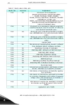
Страница 60: ...cksum error Data pointer lost 4 System param eter checksum error for default page and m ultim onitoring 5 Application defined power down variable checksum error for counter or reference 6 Application defined param eter variable checksum error for counter or reference 10 System param eter checksum error for fault history entries or system m enu param eter 2 Critical fault 10 Critical fault Other An...

Страница 61: ...rvice phone 358 0 40 83 71 150 62 4 F24 Counter fault F24 displayed Check logged data fault history Error reading operating time or MWh counter Internal fault on control board possible or one time error reading data FIGURE 21 Fault code F24 ...

Страница 62: ...g fault F25 displayed Check logged data in fault history NOTE 1 Cpu watchdog timer 2 Asic reset 11 14 NXS special codes 31 51 NXP special codes NOTE If this fault occurs in particular situation Store parameter setting and contact software vendor Update software Check subcode Internal fault due to control board failure or software fault F25 again No fault Trip occurring just once YES NO FIGURE 22 F...

Страница 63: ...6 displayed Check logged data in fault history F26 Start up prevented NOTE Software trigged fault Fault can occure in overvoltage situation If a variable changes during overvoltage then F2 is replaced by F26 Fault is to be considered as information only FIGURE 23 Fault code F26 ...

Страница 64: ...fault F29 displyed Checked logged data in fault history Check thermistor connection and motor temperature Thermistor input on option board detected this fault External fault Correct the thermistor or cooling of the motor NOTE Thermistor input has to be shortcircuited if thermistor not used FIGURE 24 Fault code F29 ...

Страница 65: ...mpare to monitoring page NOTE F31 occurs only from FR9 and bigger frame sizes CH61 and bigger chassis NOTE If F31 and F41 occurs at the same time Use F41 troubleshooting F31 displayed Check logged data in fault history Internal fault Check temperature measurement circuit or drive is too small Parameter setting generated this fault External reason generated this fault Problem with motor or output f...

Страница 66: ...th such F32 displayed Check logged data in fault history Fan does not start when ON command is given Check fan inverter for visible damage Disconnect and check fan Measure winding resistance and insulation resistance W ere all measurem ents OK Power drive with fan disconnected Fan inverter fault Also check fan capacitor Replace faulty fan Check at least fan capacitor and fan inverter Powersupply f...

Страница 67: ...CAN communication fault F34 displayed Check logged data in fault history Sent message is not acknowledged Reconfigure one of the drives which has got double setting Check cable condition and connections Are there other drives with same configuration NO YES FIGURE 27 Fault code F34 ...

Страница 68: ... a d e d C h e ck su b co d e a n d co n ta ct a p p lica tio n d eve lo p er if p ro b le m o ccu rs se ve ra l tim e s N O T E S u b co d e 8 9 O ve rlo ad o n 1 m s leve l S u b co d e 9 0 O ve rlo ad o n 5 m s leve l S u b co d e 9 1 O ve rlo ad o n 1 0m s le vel S u b cod e 9 2 O ve rlo a d o n 1 0 0 m s leve l S u b cod e 9 3 O ve rlo a d o n 1 0 0 0 m s le ve l S u b co d e 9 5 A pp lica ti...

Страница 69: ...unit data and correct wrong setting NOTE Software is incompatible with existing power unit Did fault occure at first power up after service been performed Was an eeprom reprogramed Entered EEPROM data incompatible with existing system software Replace the board with corrupted EEPROM if it can not be reprogramed EEPROM corrupted NO YES code F35 FIGURE 29 Fault code F36 ...

Страница 70: ...F37 displayed Check subcode NOTE Subfaultcode displayed 1 Control board 2 Control unit 3 Power board 4 Power unit 5 Adapter board A Slot A B Slot B C Slot C D Slot D E Slot E Indication only no fault Indicaton should appear when same type of device with different serial number has been changed FIGURE 30 Fault code F37 ...

Страница 71: ... Device added F38 displayed Check subcode NOTE Subfaultcode displayed 1 Control board 2 Control unit 5 Adapter board A Slot A B Slot B C Slot C D Slot D E Slot E Indication only no fault Indicaton should appear when option board or adapter has been added FIGURE 31 Fault code F38 ...

Страница 72: ...x 358 0 204 335 091 73 4 F39 Device removed F39 displayed Check subcode NOTE Subcode displayed 5 Adapter board A Slot A B Slot B C Slot C D Slot D E Slot E Indication only no fault Indicaton should appear when optionboard or adapter has been removed FIGURE 32 Fault code F39 ...

Страница 73: ...is not valid Replace the board with corrupted EEPROM if it can not be reprogrammed EEPROM corrupted NO YES NOTE Subfcode displayed 1 Control board 2 Control unit 3 Power board 4 Power unit 5 Adapter board A Slot A B Slot B C Slot C D Slot D E Slot E EEPROM data on a board is invalid Did you program the EEPROM or is it factory preprogrammed EEPROM is not programed Program it according to valid inst...

Страница 74: ... to describe temperature rise of the IGBT s W hen unit trips and goes into standby mode the values is stored Parameters to check are acceleration time U f curve current limit DC braking or switching frequency Software has detected too high short term overload NO YES W as measured values monitored value YES Actual overload caused the trip Decrease load or make changes to parameter settings Drive ca...

Страница 75: ...e can appear only when internal brake resistor and internal brake chopper is used Software has detected too high temperature on internal brake resistor Increase decceleration time and start again Install properly dimensioned external external brake resistor and make parameter changes F42 again Wrong parameter setting NO NO YES Fault occurred due to wrong dimensioning of brake resistor YES YES FIGU...

Страница 76: ...de Visible fault on encoder cable NOTE 1 Channel A missing 2 Channel B missing 3 Both channels missing 4 Encoder reversed 5 Board is missing Take corrective actions based on subcode Check state of optioncard Encoder or cabling fault Pulses OK Optioncard faulty YES YES NO NO Measure encoder pulses Is status run NO YES FIGURE 36 Fault code F43 ...

Страница 77: ... F44 appears when power unit of different size or voltage is connected to same control unit F44 appears if new option board is of different type 1 Control board 2 Control unit 3 Power board 4 Power unit 5 Adapter board A Slot A B Slot B C Slot C D Slot D E Slot E Press reset Drive will now have default parameters Set needed parameters YES NO Store parameters to panel or PC Press reset Download par...

Страница 78: ... Service Bulletin 0303 Available in software NXSV128 NXPV122 or newer F45 appears if new option board of different type is inserted in same slot Option board parameters are set to default 1 Control board 2 Control unit 3 Power board 4 Power unit 5 Adapter board A Slot A B Slot B C Slot C D Slot D E Slot E Press reset Set option board prameters as needed FIGURE 38 Fault code F45 ...

Страница 79: ... 83 71 150 80 4 F50 Analogue input 4mA F50 displayed Check data in fault history External fault Replace mA sensor or its cable Value 4mA Measure input value at corresponding I O terminal Internal fault Replace faulty option board NO YES FIGURE 39 Fault code F50 ...

Страница 80: ...091 81 4 F51 External fault F51 displayed Check data in fault history External fault Replace external appliance or its cable Value OK Measure input value at corresponding I O terminal Note F51 can be used as CC or OC Internal fault Replace faulty optionboard NO YES FIGURE 40 Fault code F51 ...

Страница 81: ...lt history Communication faulty in panel or control board Empty panel Possible fault locations are at cable between panel and control board or on the control board NO YES NOTE Fault can occur when the panel is active control place Measure 9V between pins 1 and 2 on connector 9V present YES Faulty control board NO FIGURE 41 Fault code F52 ...

Страница 82: ...history Fieldbus option board faulty Cables OK Fault in the fieldbus of themaster Reset of master needed YES Check fieldbus communication status from option board hardware or software Communication OK YES Non shielded fieldbus cables disturbance or poor earth connection NO Check cables and earth connections NO Check if drive recognizes the option board Board recognized YES NO ...

Страница 83: ...tion YES Start up of new option board Did fault occur when a new optionboard was plugged in NO Check for RUN status on each optionboard NO NOTE Fault occurs when internal SPI bus is overloaded or broken SPI bus communicates with slots B E YES Initialisation state is active on option board but does not reach RUN state Application might communicate with option board too many times time slot Applicat...

Страница 84: ...85 4 FIGURE 44 Fault code F56 F56 PT 100 fault F56 displayed Check data in fault history Hardware fault on option board Source is outside limits for a reason Correct the external cause Temperature limit have exeeded the board parameters Check PT 100 temperature Temperature within limits NO YES ...

Страница 85: ...paremeter values and correct them if needed Hardware or software trip 2 Check that the unit has been dimensioned correctly 3 Check hardware IGBT power board con trol board ASIC board SC motor cable and the motor S2 1 Power 1 Unit Appears in the NXS unit only 1 Check the parameter values 2 Check that the unit size is correct to the use 3 Check hardware IGBT power board con trol board ASIC board S3 ...

Страница 86: ...t type does it include a brake chopper and a resistor S2 1 Power 1 Unit U 2 t protec tion In the unit 690V DC link voltage has been over 1100V too long time Over voltage protec tion of DC link capacitors 1 Check the parame ters Change longer Decel eration time Check if the brake chopper is in use 2 Reboot the unit 3 Defect apperas out side of the unit Mains changes voltage spikes in supply volt ag...

Страница 87: ...f the fault is real the chargain relay will failured Sometimes its feedback prob lem from the charging relay Signal ASIC STR only in run mode Check the control board Check the feedback the cable connection between the control board and the power board F6 Emer genc y Stop S1 5 Expan der 2 Board Fault is trigged from the PIN 6 in each I O slot Signal is not used in stan dard I O boards Signal ASIC O...

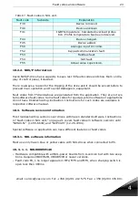
Страница 88: ...lt might be on the power board in the power mod ule in the IGBT or in the internal cables Some times short cir cuit fault appears simulta neously with F7 If there is a brake chopper in use check the isolation resistance and resistance on the brake resistor FR4 FR8 measure the power module directly from its terminals Check the capasitors TABLE 16 System software fault codes Code Sub code Module Sub...

Страница 89: ... FR8 if the boards VB00449 VB00450 in use failure might be there S2 4 Con trol 2 Board Microprocessor watchdog fail ure in the ASIC circuit Failure has been dis ablerd but if it appears anyway 1 Check if the failure is recursive 2 Check the ground ings 3 Reload the software 4 Change the control board S3 4 Con trol 2 Board FR8 FR14 units which includes adapter board VB00449 VB00450 Vacon bus watchd...

Страница 90: ...ich includes star coupler There is MOX contactors 1 2 3 4 inside the ASIC board VB00451 which is are not swap in time 1 Check the fibres con nections connectors on the ASIC board VB00451 2 Check the connection between control board and adapter board VB00228 3 Check the connections of the optical fibres S6 1 Power 1 Unit Feedback of the charging relay does not work correctly Fail ure appears in the...

Страница 91: ...it 2 U phase 3 V phase 4 W phase Driver board without auxil iary voltage Failure appears in the unit sizes FR9 FR14 Sig nal ASIC TRIN 1 Check the phases U V W Check the ASIC board VB00451 3 Check connections and connectors of the optical fibres F9 S1 1 Power 1 Unit DC voltage too low in run state S2 1 Power 2 Power 1 3 Power 2 1 Unit S3 1 Power 1 Unit UV Fast Stop F10 S1 1 Power 2 Power 1 3 Power ...

Страница 92: ...e 4 V phase 5 W phase F14 S1 1 Power 2 Power 1 3 Power 2 1 Unit 2 Board 3 U phase 4 V phase 5 W phase S2 1 Power 2 Board ASIC TRIN Ter mistor on power board F15 S1 9 Motor F16 S1 9 Motor F17 S1 9 Motor F18 S1 1 Power 1 Unit Current S2 1 Power 1 Unit Voltage TABLE 16 System software fault codes Code Sub code Module Sub module Explanation Fault mode ...

Страница 93: ...r S4 4 Con trol 2 Board System parame ter checksum error multimon itor panel default pages S5 4 Con trol 2 Board Application defined power down variable checksum error S6 4 Con trol 2 Board Application defined power down variable checksum error S10 4 Con trol 2 Board System parame ter checksum error fault his tory entries device valid system menu parameters F24 S1 4 Con trol 2 Board Operating time...

Страница 94: ... asic circuit F26 S1 8 Soft ware 11 Appl ication Prevention of accidental start up F31 S1 1 Power 2 Power 1 3 Power 2 1 Unit 3 U phase 4 V phase 5 W phase Available from FR9 F32 S1 1 Power 2 Power 1 3 Power 2 1 Unit Fan does not work according to feedback information although requested F34 S1 5 Expan der 2 Board F35 S1 Sxx 8 Soft ware 11 Appl ication Priority problem in application S97 8 Soft ware...

Страница 95: ...xpan der 6 Adapt er 7 Star coupler 1 Unit 2 Board 6 A slot 7 Blot 8 C slot 9 D slot 10 E slot Paramters remains the same F38 S1 1 Power 2 Power 1 3 Power 2 4 Con trol 5 Expan der 6 Adapt er 7 Star coupler 1 Unit 2 Board 6 A slot 7 Blot 8 C slot 9 D slot 10 E slot Only after micro processor reset TABLE 16 System software fault codes Code Sub code Module Sub module Explanation Fault mode ...

Страница 96: ...04 335 091 97 4 F39 S1 1 Power 2 Power 1 3 Power 2 4 Con trol 5 Expan der 6 Adapt er 7 Star coupler 1 Unit 2 Board 6 A slot 7 Blot 8 C slot 9 D slot 10 E slot Only after micro processor reset TABLE 16 System software fault codes Code Sub code Module Sub module Explanation Fault mode ...

Страница 97: ... 2 Board Power 2 not equal to Power 1 Only after microprocessor reset S3 7 Star coupler NXP2 required with star cou pler Only after microprocessor reset S4 4 Con trol Wrong device data for Control card or Control unit Only after microprocessor reset S5 4 Con trol 2 Board Wrong size eeprom on NXP controlboard NXP0000V152 or newer software require 32kbyte eeprom Only after micropro cessor reset F41 ...

Страница 98: ... S3 5 Expan der 8 C slot Channel A and B missing S4 5 Expan der 8 C slot Reversed S5 5 Expan der 8 C slot Card missing S6 5 Expan der 8 C slot Serial communi cation fault S7 5 Expan der 8 C slot A and B mis matched S8 5 Expan der 8 C slot Resolver motor pole pair mis match S9 5 Expan der 8 C slot Missed start angle TABLE 16 System software fault codes Code Sub code Module Sub module Explanation Fa...

Страница 99: ...slot 9 D slot 10 E slot Unit parameter will go to fac tory default Only after micro processor reset F45 S1 1 Power 2 Power 1 3 Power 2 4 Con trol 5 Expan der 6 Adapt er 7 Star coupler 1 Unit 2 Board 6 A slot 7 Blot 8 C slot 9 D slot 10 E slot F49 S1 8 Soft ware 11 Appl ication Division by 0 in application TABLE 16 System software fault codes Code Sub code Module Sub module Explanation Fault mode ...

Страница 100: ...Fault codes and software email service vacon com Tel 358 0 201 212 575 Fax 358 0 204 335 091 101 4 ...

Страница 101: ...tion boards 24h on call service phone 358 0 40 83 71 150 102 5 11 SERVICE INSTRUCTIONS FOR OPTION BOARDS 11 1 Basic tests 11 1 1 Control board interface diagram FIGURE 45 Control board measurement points ...

Страница 102: ... They can be used to load programs and run diagnostics to the PC FIGURE 46 VB300 and 3BOXTEST 11 1 2 1 3 VB300 Power board simulator for NXS NXP The tool simulates power board for imitation unit temperature DC link voltage etc It imitates also different power unit faults like F9 Under voltage F1 Over current F32 Fan alarm etc External 24 V DC required FIGURE 47 Test tool and NX control board conne...

Страница 103: ...hite Pink Yellow Green Brown White Blue Pink Brown White Black Brown Blue White Red Brown Red Yellow Brown Grey Brown 10Vref AI1 AI1 AI2 AI2 24Vout bi directional GND DIN1 DIN2 DIN3 CMA 24Vout bi directional DIN4 DIN5 DIN6 CMB AO1 use GND for AO1 DO1 Red Blue White Green Brown Green White Yellow White Grey White RO1 Normal closed RO1 Common RO1 Normal open RO2 Normal closed RO2 Common RO2 Normal o...

Страница 104: ...sting the Eprom by Device Properties program The device properties program is used to get more specified information about option boards PC will be needed 11 2 NX option boards Option board manuals are available on the site www vacon com Support Downloads Vacon manuals 6 Option Board User s Manuals ...

Страница 105: ... encoder 5 24V NXP NX OPT A5 VB00267J UD00741J I O Expander options for NX Basic I O DER Double Encoder with Repater NX OPT A7 VB00297H UD00741J I O Expander options for NX Basic I O 6xDI 1xDO 2xAI 1xAO 10V ref 24V ext isolated NX OPT A8 VB00280L UD00741J I O Expander options for NX Basic I O 6xDI 1xDO 2xAI 1xAO 10V ref 24V ext NX OPT A9 VB00283G UD00741J I O Expander options for NX Basic I O 3xDI...

Страница 106: ...5 091 107 5 SINCOS Encoder board NX OPT AK VB00245CA UD01182A OPT AK BE BG Motion feedback options Basic I O module NX OPT AL VB00471B UD00741J I O Expander options for NX TABLE 17 Basic I O boards NX OPT A_ Basic I O boards NX OPT A_ OPT Type Valid board ver sion User s manual ...

Страница 107: ...ed AI and 2 galvanically iso lated AO standard signals 0 4 20 mA NX OPT B4 VB00256M UD00741J I O Expander options for NX I O expander board 3xRO NX OPT B5 VB00260F UD00741J I O Expander options for NX Temperature mea suring board with 3 PT 100 sensor 3 wire inputs Expander I O 3xPT 100 I O expander board 5x42 240V AC DI NX OPT B8 VB00290K UD00741J I O Expander options for NX 1xRO Expander I O 1xRO...

Страница 108: ... 5 SSI and Endat encoders NX OPT BE VB00244CA UD01182A OPT AK BE BG Motion feedback options Resolver board 2 NX OPT BG VB00433A UD01182B OPT AK BE BG Motion feedback options TABLE 18 I O Expander boards NX OPT B_ I O Expander boards NX OPT B_ OPT Type Valid board ver sion User s manual ...

Страница 109: ... NX OPT C4 VB00263F UD00887C OPT C4 LonWorks option Profibus DP D9 type connector NX OPT C5 VB00279H UD00711I OPT C3 C5 Profibus option Can Open slave NX OPT C6 VB00277F UD00709D OPT C6 CanOpen option DeviceNet NX OPT C7 VB00281G UD00759E OPT C7 DeviceNet option RS 485 Multicon trol D9 type con nector Modbus N2 NX OPT C8 VB00282E UD00972C OPT C2 C8 Modbus N2 option S2 protocol board SELMA NX OPT C...

Страница 110: ...tions for NX SystemBus adapter 1xfibre optic pair CAN BUS adapter gal vanically decoupled NXP NX OPT D2 VB00276F UD00741J I O Expander options for NX RS 232 adapter board galvanically decoupled mainly used in application engi neering to con nect keypad NX OPT D3 VB00261G UD00741J I O Expander options for NX CANBUS adapter galvanically decoupled NXP NX OPT D6 VB00338E UD00741J I O Expander options ...

Страница 111: ... the drive does not have a DC terminal Set the power supply voltage setting to zero and switch on the DC power supply Increase the voltage slowly to the units nominal DC voltage 1 35 x Un Read the following monitoring and system info values The Voltage of the DC link is 1 8 the same as the supplied DC voltage The Unit temperature is V1 9 estimate if it corresponds to environmental tempera ture The...

Страница 112: ...parameters e g motor Do not set a too high value for the current limit P2 1 5 a too short time for acceleration time P2 1 3 or a too short time for deceleration time P2 1 4 Run the motor without a load between the minimum and maximum frequency and measure the output current with a current clamp Compare the current clamp values to unit s monitoring value V1 4 Load the motor to the nominal value if ...

Страница 113: ...VACON Plc Runsorintie 7 65380 Vaasa Finland Subject to change without prior notice 2008 Vacon Plc SM00002 D 20 08 2008 Author Jaana Kukkonen ...

Отзывы: