PC
BOARDS
Service Manual M4 - M10
22.10.2001
Page
95
9.3.4 Schematic diagrams
NOTE! Schematic diagrams are not distributed to Service Centres. In case of
Schematic diagrams are needed these can be requested from Producer.
9.3.5 Troubleshooting
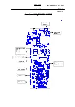
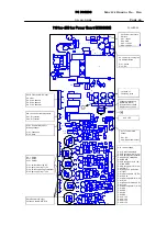
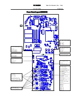
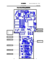
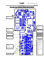
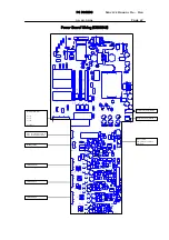
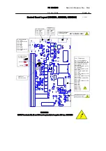
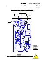
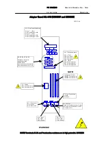
Troubleshooting of the Control board can be carried out by checking signals
and supply voltages at terminals on the board. The signals and voltages can
be measured from terminals on the board, which procedure is comprehensive
enough to determine operation of the circuitry. Signals and voltages are
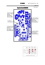
described on the layout drawings of the particular boards.
Operation of process interface can be checked by monitoring statuses of
inputs and outputs on display, as well as analog signals on input and output
terminals.
9.3.6 Replacement of Control Board
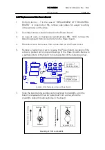
1.
Make sure unit is unpowered and possibly used bypass circuit does not
feed back energies to the drive.
2.
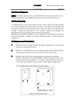
Remove a control panel from bracket by squeezing the locking clips on
both sides of the panel to direction of centre line of the panel.
3.
Remove cover of the drive by loosening screws three full rounds
counter clock wise in units up to 90kW. In cases of larger drives, screw
the fastening screws until cover is released. Do not pull the screws out.
The screws are locked in holes to avoid unintentional dropping off.
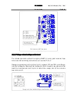
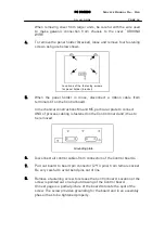
Look at figure below for locations of the screws.
Ground wire for cover!
Locations of the fastening screws
Содержание CX
Страница 1: ......
Страница 33: ...TROUBLESHOOTING Service Manual M4 M10 11 07 2002 Page 33 ...
Страница 34: ...TROUBLESHOOTING Service Manual M4 M10 11 07 2002 Page 34 ...
Страница 148: ...SPARE PART LISTS Service Manual M4 M10 Page 148 ...

