background image

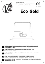
Eco Gold

IL n. 150
EDIZ. 02/05/2006

V2 ELETTRONICA SPA

Corso Principi di Piemonte, 65/67 - 12035 RACCONIGI (CN) ITALY

tel. +39 01 72 81 24 11    fax +39 01 72 84 050

[email protected]    www.v2home.com

ATTUATORE ELETTROMECCANICO IRREVERSIBILE PER CANCELLI SCORREVOLI 
FINO A 600 KG DI PESO

ELECTRO-MECHANICAL IRREVERSIBLE ACTUATOR FOR SLIDING GATES 
UP TO 600 KG OF WEIGHT

OPÉRATEUR ÉLECTROMÉCANIQUE IRRÉVERSIBLE POUR PORTAILS COULISSANTS 
JUSQU’ À 600 KG

ELEKTROMECHANISCHER NICHT UMKEHRBARER STELLANTRIEB FÜR
ZAHNSTANGESCHIEBETORE MIT MAXIMALEM GEWICHT VON 600 KG

MOTORREDUCTOR ELECTROMECÁNICO IRREVERSIBLE PARA PUERTAS CORREDERAS
HASTA 600 KG DE PESO

I

GB

F

D

E


Содержание Eco Gold

Страница 1: ...RSIBILE PER CANCELLI SCORREVOLI FINO A 600 KG DI PESO ELECTRO MECHANICAL IRREVERSIBLE ACTUATOR FOR SLIDING GATES UP TO 600 KG OF WEIGHT OPÉRATEUR ÉLECTROMÉCANIQUE IRRÉVERSIBLE POUR PORTAILS COULISSANTS JUSQU À 600 KG ELEKTROMECHANISCHER NICHT UMKEHRBARER STELLANTRIEB FÜR ZAHNSTANGESCHIEBETORE MIT MAXIMALEM GEWICHT VON 600 KG MOTORREDUCTOR ELECTROMECÁNICO IRREVERSIBLE PARA PUERTAS CORREDERAS HASTA ...

Страница 2: ... TECHNISCHE EIGENSCHAFTEN 20 VORBEREITENDE ARBEITSSCHRITTE 21 INSTALLATION 21 MONTAGE DER ZAHNSTANGE 21 INSTALLATION DER ENDANSCHLÄGE 21 MOTORFREIGABE 22 INSTALLATIONSPLAN 22 BESCHREIBUNG DER STEUERZENTRALE 23 E ADVERTENCIAS IMPORTANTES 25 CONFORMIDAD A LAS NORMATIVAS 25 LISTA DE COMPONENTES 26 CARACTERÍSTICAS TÉCNICAS 26 OPERACIONES PRELIMINARES 27 INSTALACIÓN 27 MONTAJE DE LA CREMALLERA 27 INSTA...

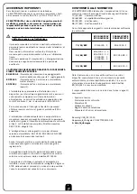
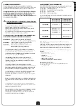
Страница 3: ...e qualificato in grado di rilasciare la dichiarazione di conformità di tipo A sull installazione completa Direttiva macchine 98 37 EEC allegato IIA E obbligo attenersi alle seguenti norme per chiusure veicolari automatizzate EN 12453 EN 12445 EN 12978 ed alle eventuali prescrizioni nazionali Anche l impianto elettrico a monte dell automazione deve rispondere alle vigenti normative ed essere esegui...

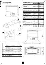
Страница 4: ...cancello 600 Kg 600 Kg Alimentazione 230VAC 50Hz 120VAC 60Hz Potenza massima 500 W 500 W Assorbimento a vuoto 1 6 A 3 2 A Assorbimento a pieno carico 2 A 4 A Condensatore 16 µF 40 µF Velocità massima anta 0 16 mt sec 0 16 mt sec Spinta massima 480 N 480 N Ciclo di lavoro 30 30 Pignone M4 Z12 M4 Z12 Temperatura di esercizio 20 C 60 C 20 C 60 C Peso del motore 10 Kg 10 Kg Protezione IP44 IP44 Carico...

Страница 5: ...ue ancoraggi a tassello in corrispondenza dei fori predisposti B Fissare il motore sulla contropiastra tramite gli appositi dadi a gabbia incastrati nei fori C MONTAGGIO DELLA CREMAGLIERA Sbloccare il motore e posizionare il cancello in posizione totalmente aperto Fissare tutti gli elementi della cremagliera al cancello facendo attenzione di mantenerli alla stessa altezza rispetto al pignone motor...

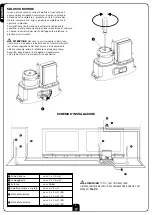
Страница 6: ...IONE Nel caso in cui il cancello superi il suo limite di corsa andando in battuta contro il fermo di arresto es errata regolazione dei finecorsa e sia necessario lo sblocco manuale prima di utilizzare la procedura sopra descritta riposizionare l anta agendo manualmente sull albero rotore 2 per mezzo di un cacciavite m ATTENZIONE TUTTI I CAVI UTILIZZATI PER L INSTALLAZIONE DEVONO ESCLUSIVAMENTE ESS...

Страница 7: ...allo spegnimento del led L1 il led si spegne per circa 1 2 secondo indicando la corretta memorizzazione del codice Immediatamente il led ricomincia a lampeggiare per un numero di volte pari alla zona di memoria appena occupata Terminati i lampeggi il sistema è pronto per l utilizzo IMPORTANTE ogni codice memorizzato è associato unicamente al comando di START MODALITÀ ROLLING CODE È possibile abili...

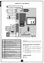
Страница 8: ...a Contatto normalmente chiuso 14 Schermatura cavo antenna 15 Antenna m ATTENZIONE Gli ingressi normalmente chiusi STOP FOTOCELLULA se non sono utilizzati devono essere ponticellati con il COMUNE INDICATORI DI STATO DEGLI INGRESSI L1 Programmazione L2 Si accende quando riceve un impulso sull ingresso di START L3 Si spegne quando riceve un impulso sull ingresso di STOP L4 Si spegne quando riceve un ...

Страница 9: ...e concerning the whole installation Machine Directive 98 37 EEC Annex IIA The automated vehicular gates shall comply with the following rules EN 12453 EN 12445 EN 12978 as well as any local rule in force Also the automation upstream electric system shall comply with the laws and rules in force and be carried out workmanlike The door thrust force adjustment shall be measured by means of a proper to...

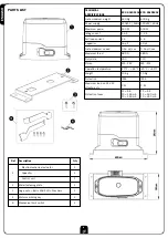
Страница 10: ... sec 0 16 mt sec Maximum thrust 480 N 480 N Duty cicle 30 30 Pinion M4 Z12 M4 Z12 Operation temperature 20 C 60 C 20 C 60 C Weight 10 Kg 10 Kg Protection IP44 IP44 Maximum load on 24 VAC attachments 3 W 3 W Protection fuses F1 5 A F2 160 mA F3 250 mA F1 5 A F2 160 mA F3 250 mA Ref Description Q ty 1 Electro mechanical actuator 1 Capacitor 1 Control unit 1 2 Metal fastening plate 1 3 Cage nuts Bolt...

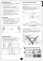
Страница 11: ...the already made holes B Fix the motor on the counter plate by means of the bolts 3 and the nuts fitted in the holes C MOUNTING THE RACK Release the motor and turn the gate completely open Fix all the rack elements to the gate making sure that they stand at the same height than the motor pinion It is important that the rack be positioned 1 or 2 mm above the motor pinion in order to prevent that th...

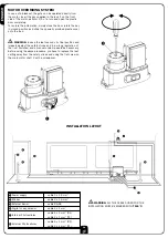
Страница 12: ...cts against the safety stroke end i e wrong regulation of the limit switches and a manual unclamp would be necessary before using the above procedure you have to replace the leaf setting away from the safety stroke end using the flat screw on the main motor shaft 2 with a screwdriver m WARNING ALL THE CABLES USED FOR THE INSTALLATION MUST BE MARKED WITH T100 C INSTALLATION LAYOUT 1 Power supply ca...

Страница 13: ...ssed until the led L1 lightens Keep the button of the transmitter pressed until the led L1 goes off for about a 1 2 second indicating the correct memorization of the code Then the led start immediately flashing for a number of times corresponding to the number of the memory zone which has just been taken Once the flashings have ceased the system is ready to be used IMPORTANT every stored code is o...

Страница 14: ...ormally closed contact 14 Antenna cable shielding 15 Antenna m CAUTION Unused inputs that are normally closed STOP and PHOTOCELL should be connected to the common wire STATUS INDICATORS OF THE UNIT INPUTS L1 Programming L2 Lights up when a pulse is received at the START input terminal L3 Goes out when a pulse is received at the STOP input terminal L4 Goes out when a pulse is received at the PHOTOC...

Страница 15: ...ité et mécaniques doit être faite exclusivement par techniciens qualifiés en mesure de délivrer l attestation de conformité pour l installation Directive 98 37 EEC IIA Il est obligatoire se conformer aux normes suivantes pour fermetures véhiculaires automatisées EN 12453 EN 12445 EN 12978 et à toutes éventuelles prescriptions nationales Même l installation électrique ou on branche l automatisme do...

Страница 16: ...0 16 mt sec Poussée maximum 480 N 480 N Cicle de travail 30 30 Pignon M4 Z12 M4 Z12 Temperature de travail 20 C 60 C 20 C 60 C Poids 10 Kg 10 Kg Protection IP44 IP44 Charge max accessoires alimentés à 24 VAC 3 W 3 W Fusibles de protection F1 5 A F2 160 mA F3 250 mA F1 5 A F2 160 mA F3 250 mA Rif Description Q té 1 Opérateur électromécanique 1 Condensateur 1 Centrale de commande 1 2 Plaque métalliq...

Страница 17: ...laque devra être fixée au sol par l intermédiaire de deux ancrages à cheville à hauteur des trous aménagés à l avance B Fixer le moteur sur la contre plaque par l intermédiaire des écrous à cage convenables encastrés dans les trous C MONTAGE DE LA CRÉMAILLÈRE Débloquer le moteur et positionner le portail en position totalement ouverte Fixer tous les éléments de la crémaillère au portail en faisant...

Страница 18: ...lastique prévue à cet effet m ATTENTION Dans le cas que le portail va a en butées de fin de course ex mauvaise régulation des fin course avant de débloquer le moteur avec la procédure sous décrite il faut desserrer le moteur par la barre tournevis que se trouve sur arbre rotor 2 m ATTENTION TOUS LES CÂBLES UTILISÉS POUR L INSTALLATION DOIVENT EXCLUSIVEMENT ÊTRE DES CÂBLES MARQUÉS T100 C SCHÉMA D I...

Страница 19: ...ce que le led L1 s allume Maintenir la touche du transmetteur appuyée jusqu à ce que le led L1 s éteigne le led s éteint pendant environ 1 2 seconde indiquant ainsi la correcte mémorisation du code le led recommence immediatement a clignoter pour un nombre de fois egal a la zone de memoire nouvellement occupee A la fin des clignotements le système est prêt à être utilisé IMPORTANT chaque code mémo...

Страница 20: ... Contact normalement fermé 14 Blindage câble antenne 15 Antenne m ATTENTION Ponter avec le commun les entrees normalement fermees STOP et PHOTOCELLULE que ne viennent pas utilisees INDICATEURS DE L ÉTAT DES ENTRÉES SUR LA CENTRALE L1 Programmation L2 Il s éclair lorsqu il reçoit une impulsion sur l entrée de START L3 Il s éteint lorsqu il reçoit une impulsion sur l entrée de STOP L4 Elle s éteint ...

Страница 21: ... Personal durchgeführt werden welches berechtigt ist eine vollständige Konformitätserklärung vom Typ A auszustellen Maschinenrichtlinie 98 37 EEC Anlage IIA Für automatisch betriebene Rolltore ist die Einhaltung der folgenden Normen obligatorisch EN 12453 EN 12445 EN 12978 und alle eventuell geltenden regionalen Vorschriften Auch die elektrische Anlage der Automatik muss den geltenden Normen genüg...

Страница 22: ...t sec Maximaler Schub 480 N 480 N Arbeitsspiel 30 30 Antriebsritzel M4 Z12 M4 Z12 Betriebstemperatur 20 C 60 C 20 C 60 C Gewicht des Motors 10 Kg 10 Kg Schutzgrad IP44 IP44 Maximale Belastung des mit 24 VAC versorgten Zubehörs 3 W 3 W Abstellsicherungen F1 5 A F2 160 mA F3 250 mA F1 5 A F2 160 mA F3 250 mA Nr Beschreibung Menge 1 Elektromechanischen Stellantrieb 1 Kondensator 1 Zentralantrieb 1 2 ...

Страница 23: ...thilfe von Dübeln in Übereinstimmung der vorgefertigten Bohrungen B Befestigen Sie den Motor auf der Montageplatte mit den Bolzen 3 und Muttern in den dazu vorgesehenen Löchern MONTAGE DER ZAHNSTANGE Geben Sie den Motor frei und öffnen Sie das Tor ganz Befestigen Sie alle Bestandteile der Zahnstange am Tor achten Sie dabei darauf dass sich alle Elemente auf gleicher Höhe im Verhältnis zum Antriebs...

Страница 24: ...deckung wieder zu schließen den Schlüssel in die Anfangsposition zurück zu drehen und die Kunststoffkappe wieder über das Schloss zu schieben m ACHTUNG Sollte das Tor gegen den Stopper des Endanschlags gestoßen werden z B aufgrund der mangelhaften Regulierung des Endanschlags muss der Motor vor der Freigabe durch die oben beschriebene Prozedur mittels Einwirkung auf den Schraubenschlitz an der Rot...

Страница 25: ...2 Sek lang erloschen und zeigt so die korrekte Speicherung des Codes an SOFORT DANACH BEGINNT DAS LED ERNEUT MIT EINER BLINKREIHE DEREN ANZAHL DER NUMMER DES SOEBEN BESETZTEN SPEICHERPLATZES ENTSPRICHT Nach Beendigung der Blinkvorgänge ist das System einsatzbereit WICHTIG Jeder gespeicherte Code bezieht sich lediglich auf den Befehl START ROLLING CODE MODALITÄT Die ROLLING CODE Modalität kann ein ...

Страница 26: ... Antenne m ACHTUNG VERBINDEN SIE DIE NORMALERWEISE GESCHLOSSENEN STOP und FOTOZELLEN NICHT VERWEN DETEN EINGÄNGE MIT DEN KLEMMEN ALLGEMEIN STATUSAZEIGEN DER EINGÄNGE AN DER ZENTRALE L1 Programmierung L2 Schaltet sich ein wenn ein Impuls am Eingang START empfangen wird L3 Schaltet sich aus wenn ein Impuls am Eingang STOP empfangen wird L4 Schaltet sich aus wenn ein Impuls am Eingang PHOTO empfangen...

Страница 27: ...ón de conformidad en la instalación Directiva máquinas 98 37 EEC anexo IIA Es obligatorio atenerse a las siguientes normas para cierres automatizados con paso de vehículos EN 12453 EN 12445 EN 12978 y a las eventuales prescripciones nacionales Incluso la instalación eléctrica antes de la automatización debe responder a las vigentes normativas y estar realizada correctamente La regulación de la fue...

Страница 28: ...c Empuje máximo 480 N 480 N Ciclo de trabajo 30 30 Piñón M4 Z12 M4 Z12 Temperatura de funcionamiento 20 C 60 C 20 C 60 C Peso motor 10 Kg 10 Kg Grado de protección IP44 IP44 Carga máx accesorios alimentados a 24 VAC 3 W 3 W Fusibles de protección F1 5 A F2 160 mA F3 250 mA F1 5 A F2 160 mA F3 250 mA Rif Descripción Cant 1 Motorreductor electromecánico 1 Condensador 1 Cuadro de maniobras 1 2 Placa ...

Страница 29: ...endo con los agujeros predispuestos B Fijar el motor a la placa con sus proprios tornillos 3 y los dados fijados en los agujeros C MONTAJE DE LA CREMALLERA Desbloquear el motor y posicionar la puerta en posición totalmente abierta Fijar todos los elementos de la cremallera a la puerta teniendo el cuidado de mantenerla toda al mismo nivel con respecto al piñón del motor Es importante que la cremall...

Страница 30: ... m CUIDADO En el caso de que la puerta corredera toque con el tope de final de carrera ej por una regulación errónea del final de carrera antes de desbloquear el motor con el procedimiento descrito anteriormente aflojar el motor girando el tornillo puesto encima del rotor 2 m ATENCIÓN TODOS LOS CABLES UTILIZADOS PARA LA INSTALACIÓN DEBEN SER EXCLUSIVAMENTE CABLES MARCADOS T100 C ESQUEMA DE INSTALA...

Страница 31: ...L1 Mantener pulsado el pulsador del emisor hasta el apagado del led L1 el led se apaga durante cerca de 1 2 segundo indicando la correcta memorización del código Inmediatamente el led empieza a destellar por un número de veces igual a la zona de memoria recién ocupada Terminados los destellos el sistema está listo para su utilización CUIDADO cada código memorizado está asociado únicamente al coman...

Страница 32: ...3 Fotocélula Contacto normalmente cerrado 14 Malla antena 15 Positivo antena m CUIDADO Puentar con el COMUN las entradas en normalmente cerrado STOP y FOTOCÉLULA que no se utilizan INDICADORES DEL ESTADO DE LAS ENTRADAS EN EL CUADRO L1 Programación emisores L2 Se enciende cuando recibe un impulso en la entrada de START L3 Se apaga cuando recibe un impulso en la entrada de STOP L4 Se apaga cuando r...

Страница 33: ......

Страница 34: ...V2 ELETTRONICA SPA Corso Principi di Piemonte 65 67 12035 RACCONIGI CN ITALY tel 39 01 72 81 24 11 fax 39 01 72 84 050 info v2elettronica com www v2home com ...

Отзывы: