2 -Wire Intercom System
DT596(F)KP User Manual
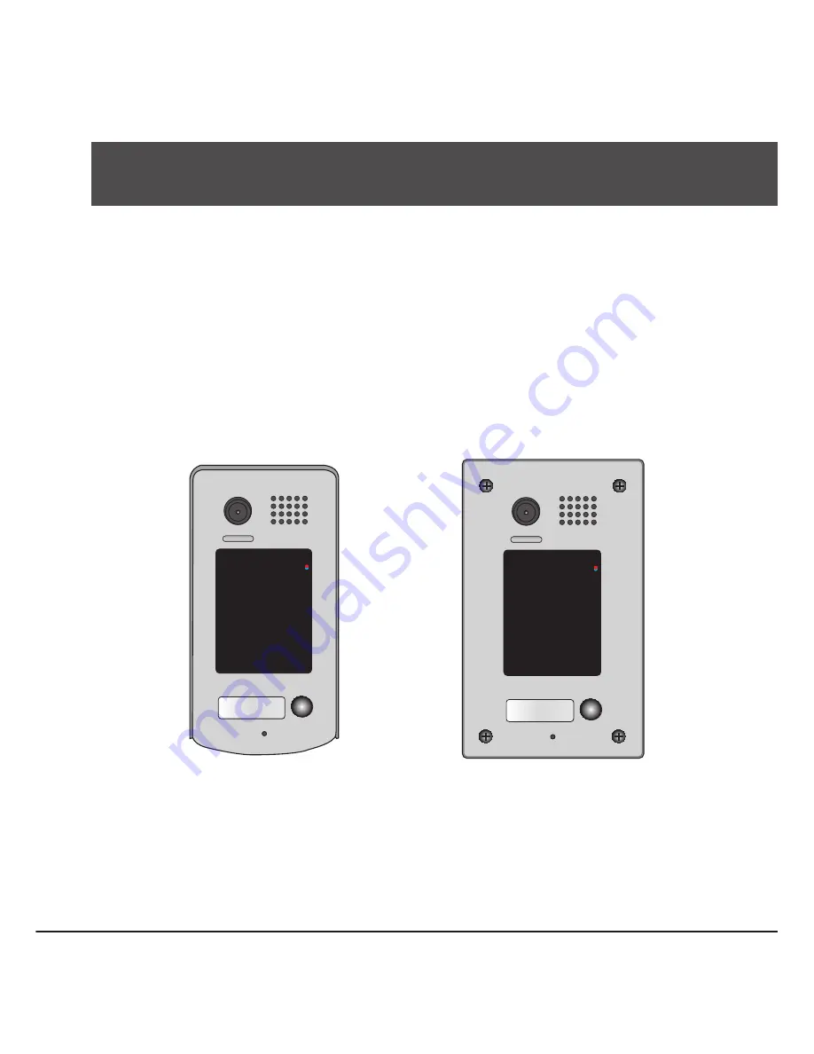
DT596/KP
DT596F/KP
DT-ENG-596(F)KP-V2 110S714
14 5 6
9
80 #
7
*
2 3
Страница 1: ...2 Wire Intercom System DT596 F KP User Manual DT596 KP DT596F KP DT ENG 596 F KP V2 110S714 1 4 5 6 9 8 0 7 2 3 1 4 5 6 9 8 0 7 2 3...
Страница 2: ...escriptions 1 3 Door Station Mounting 2 4 System Wiring and Connections 4 5 DIP Switches Setting 11 6 Functions Setting Up 12 7 Unlock Operations 18 8 Power Supply Instructions 19 9 Precaustions 19 10...
Страница 3: ...ue Nameplate Call Button Microphone 90 mm 28 mm 176 mm 220 mm 119 mm 1 4 5 6 9 8 0 7 2 3 1 4 5 6 9 8 0 7 2 3 Camera Lens Touch Sensitive Digital Keypad Speaker Nameplate Call Button Screws for panel m...
Страница 4: ...power positive power S1 S2 Lock power output to connect 2 locks S Lock power output connect to the power input of locks only when using the camera to power the locks if using the external power suppl...
Страница 5: ...ach to the wall Attach the panel to the mounting box and use screws supplied to fix the panel Place name label Connect the cable correctly and adjust right angle for camera adjust camera angle PS Adju...
Страница 6: ...iring and Connections AC monitor DPS PS4 L1 L2 PL S1 S2 S Placing Name Label Move the plastic cover away to open the transparent name label cover insert a name paper then put the plastic cover back to...
Страница 7: ...ault EB LOCK BUS PL S1 S2 S LOCK 2nd 1ST 2nd EB 1ST Jumper position in Connect two locks 2 3 1 2 3 EB LOCK BUS PL S1 S2 S Jumper position in Connect one lock 2 3 1 2 3 Door Lock Controlled with Dry Co...
Страница 8: ...eypad and setting instructions will be showed Manual Monitor Monitor Memory Playback Album User Setup 09 30 2010 Thu 16 41 Close Intercom Multimedia About H W a1 3 S W V17 11 418 00 Local addr Unlock...
Страница 9: ...nnection 85 260VAC DPS PS5 monitors L1 L2 PL S1 S2 S L1 L2 PL S1 S2 S L1 L2 PL S1 S2 S L1 L2 PL S1 S2 S 1 2 3 4 ON 1 2 3 4 ON 1 2 3 4 ON 1 2 3 4 ON 1 Camera ID 00 ID 10 ID 01 ID 11 2 Camera 3 Camera 4...
Страница 10: ...T Wiring Mode Multi Monitors Connection Code 0 DIP 6 off Code 14 DIP 6 off Code 15 DIP 6 on 1 2 3 4 5 6 ON 1 2 3 4 5 6 ON 1 2 3 4 5 6 ON monitor monitor monitor 1 2 3 4 ON ID 00 85 260AC DPS PS5 1 4 5...
Страница 11: ...4 A B C D IN OUT 85 260AC DPS PS5 1 2 3 4 5 6 ON 1 2 3 4 5 6 ON 1 2 3 4 5 6 ON 1 2 3 4 5 6 ON Code 15 DIP 6 on Code 13 DIP 6 on Code 3 DIP 6 on Code 1 DIP 6 on 1 2 3 4 5 6 ON 1 2 3 4 5 6 ON 1 2 3 4 5...
Страница 12: ...8 0 7 2 3 1 4 5 6 9 8 0 7 2 3 1 4 5 6 9 8 0 7 2 3 85 260VAC DPS PS5 1 2 3 4 5 6 ON 1 2 3 4 5 6 ON 1 2 3 4 5 6 ON 1 2 3 4 5 6 ON HI DBC 4 A B C D IN OUT Code 0 DIP 6 on CALL UNLOCK TALK MON IN USE Cod...
Страница 13: ...fourth Door Station Bit3 Activate alarm function S2 and S terminals are used to connect alarm Please note that the second lock can not be connected to the system if activate alarm function Not activa...
Страница 14: ...of each function please refer to the following table About the setting mode Input the master code to switch to the setting mode and input the corresponding setting code to perform the settings for th...
Страница 15: ...e settings 0 on 1 off on 05 7 Reset code settings 1234 06 8 function settings 0 Normal 1 Reverse Normal 07 9 Call tone settings 0 Enable 1 Disable Enable 08 10 Interference resistant grade settings Va...
Страница 16: ...p red ON blue ON Beep Beep red ON blue OFF Beep red ON blue OFF Beep red ON blue OFF Beep red ON blue OFF Beep red OFF blue OFF Beep Beep Inputting of code ex 10 range 00 or 10 99 Inputting of code ex...
Страница 17: ...e ex 1 red OFF blue OFF Beep Beep When the cancel key is pressed the LED lights off the buzzer beeps and the system exits the setting mode When there isn t any operation in 10s the LED lights off the...
Страница 18: ...ep When the cancel key is pressed the LED lights off the buzzer beeps and the system exits the setting mode When there isn t any operation in 10s the LED lights off the buzzer beeps and the system exi...
Страница 19: ...xits the setting mode red OFF blue OFF Beep Beep When input the correct temporary password to release the door the system will clear the temporary password after 60 seconds automatically But you shoul...
Страница 20: ...n Lockout is activated the relay 2 doesn t respond the second lock but responds the LOCKOUT function After continuously inputing incorrect access code 10 times LOCKOUT output and the relay 2 will be c...
Страница 21: ...dc 300mA Internal Power Number of relay circuits 2 Mounting Surface mounting DT596 KP Flush mounting DT596F KP Working temperature 10 C 45 C Dimension 176 H 90 W 28 D mm DT596 KP 220 H 119 W 52 D mm D...
Страница 22: ...quantity 20 Cable Usage A B C Twisted cable 2x0 75 mm2 60 60 30 Twisted cable 2x1 mm2 80 80 40 When Monitor quantity 20 Cable Usage A B C Twisted cable 2x1 mm2 70 30 20 Twisted cable 2x1 5 mm2 70 50 3...
Страница 23: ...Note...
Страница 24: ...The design and specifications can be modified without notice to the user Right to interpret and copyright of this manual are reserved DT ENG 596 F KP V2 110S714...
Страница 25: ...Stromversorgung 24 V ber PS4 o PS5 mit DPS Stromverbrauch 2 W Standby und 5 W im Betrieb Monitorgr e 3 5 8 89 cm Display Aufl sung 320x240 mm Abmessungen 220x105x20 mm Kabelempfehlungen...
Страница 26: ...chirm zeigt die alle in Ihren System angemeldeten User Wohnungen auf Ihren Bildschirm an Einen Namensliste erstellen sie mit der optionalen Konfigurationssoftware welche sie mittels USB Connectorkabel...
Страница 27: ...2008 eingeben Men ffnet sich Sie haben die folgen Einstellm glichkeiten 1Way 2 Way F r die Installation vom mehren Kameras Sie k nnen zwei Kameras direkt an JS OS1 und JS OS2 anschlie en Bei zwei Kame...
Страница 28: ...Mode Zum einstellen des Abwesenheitsmodus bet tigen Sie am Bildschirm Setup Men W hlen Sie dann Away Set ber hren Sie die einmal Absent ON Abwesenheitsschaltung ist aktiviert Wiedergabe der Bilder Be...