background image


P/N 146169999-10 (ML) 

• REV E • ISS 18JUN13 


5 / 36 

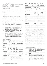
SW 4: Signaling AM or TF output 

On: Signals AM on both the AM and Alarm relays. Signals TF 
on the AM relay only (EN 50131). 

Off: Signals AM and TF on the AM relay (default). 

SW 5: Setting LEDs 

On:


Enables both LEDs on the detector at all times (default). 

Off: Puts both LEDs under the control of the Walk Test and 
Day/Night input. This activates the memory feature of the 
detector. 

AM calibration 

During start-up the AM circuitry calibrates itself to its 
environment. It is important to make sure that there are no 
changes made to the environment within 1 m distance of the 
detector within 60 s after powering up, otherwise the detector 
may be vulnerable to false AM alarms and these alarms may 
be impossible to reset. 

Configuring the coverage pattern 

• 

Remove blinders (Figure 8, item 1) if necessary. The 
modified pattern is shown in Figure 8, items 3 to 7. 

Note: 

If both blinders are installed, the detector range is 

limited to 6 m (default). 

• 

Modify the pattern by breaking out blinder parts (shown as 
gray in Figure 8, item 1). The corresponding curtain 
fragments are shown in Figure 8, item 2. 

• 

Put the appropriate mirror stickers if necessary. See 
Figure 6, item 1 for details. 

Caution: 

Removing stickers can damage the mirror 

surface. 

• 

When near objects directly under the detector, fit the mask 
to the inside of the window (default). This disables the part 
of the curtains looking down at the object, whose 
closeness might destabilize the detector. See Figure 6, 
item 2. 

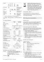
LED indication 

PIR 

Red LED 

Alarm relay 

To reset 

Start up 


Closed 

Automatically after 25 s 

Low voltage 


Open (Alarm) 

Apply correct voltage 

PIR intruder 
alarm 


Open (Alarm) 

Automatically after 3 s 


PIR/AM 

Red 
LED 

Yellow 
LED 

Alarm 
relay 

AM 
relay 

To reset 

Start up 


Closed 

Closed 

Automatically 
after 60 s  

Low voltage 


Open 
(Alarm) 

Open 
(Alarm) 

Apply correct 
voltage 

PIR intruder 
alarm 


Open 
(Alarm) 


Automatically 
after 3 s 

Latched PIR 
(Memory) 


Switch to Night 
mode 

AM alarm 


Open* 
(Alarm) 

Open 
(Alarm) 

See DIP 
switch 3 

After AM 
reset 


Switch to Night 
mode 

PIR/AM 

Red 
LED 

Yellow 
LED 

Alarm 
relay 

AM 
relay 

To reset 

Technical 
fault 


Open 
(Alarm) 

Do a successful 
walk test 

* Depends on the setting of the DIP switch SW4. 

 Continuously on   

 Normal blinking (1 Hz) 

 Fast (4 Hz) 

Specifications 


EV1012 

EV1012AM 

Detector 

PIR 

PIR + AM 

Signal processing 

DSP 

Range 

12 m 

Optical 

9 high-density mirror curtains 

Memory 

No 

Yes 

Input power 
For UL/cUL installations 

9 to 15 V

 (12 V nominal) 

10 to 15 V

 (12 V nominal) 

Peak-to-peak ripple 

2 V (at 12 V

Detector start-up time 

25 s 

60 s 

Normal current 
consumption 
For UL/cUL installations 

4.4 mA 


0.0528 W 

10 mA 


— 

Current consumption in 
alarm 

1.2 mA 

3.8 mA 

Maximum current 
consumption 

11 mA 

24 mA 

Mounting height 

1.8 m to 3.0 m (5.90 ft. to 9.84 ft.) 

Target speed range 

30 cm/s to 3 m/s  

(1 ft./s to 10 ft./s) 

20 cm/s to 3 m/s  

(8 in./s to 10 ft./s) 

Alarm (NC) / Tamper 
relay characteristic 

80 mA 

30 V

, resistive 

80 mA 

30 V


Pry-off tamper (not 
evaluated by UL/cUL) 

N/A 

Onboard (yes) 

AM relay characteristic 

— 

80 mA at 30 V

 max. 

Alarm time 

3 s 

Operating temperature 
For UL/cUL installations 

−10 to +55°C (14 to 130°F) 

0 to 49°C ( 32 to 120°F ) 

Dimensions (H x W x D) 

108 × 60 × 46 mm (4.25 × 2.36 × 1.81 in.) 

Relative humidity 

95% max. noncondensing 

(UL/cUL installations) 

Weight 

120 g (4.2 oz.) 

128 g (4.5 oz.) 

IP/IK rating 

IP30 IK02 

Regulatory information 

Manufacturer 

UTC Fire & Security Americas Corporation, Inc. 
1275 Red Fox Rd., Arden Hills, MN 55112-6943, USA 

Authorized EU manufacturing representative: 
UTC Fire & Security B.V. 
Kelvinstraat 7, 6003 DH Weert, Netherlands 

Certification 


UL/cUL 

The product must be connected to a listed burglar 
system compatible control unit or power supply unit, 
which provides a minimum 4 hours of standby power 
and has a voltage output between 10 and 15 VDC. 

All wiring must be made according to National 
Electrical Code, NFPA70, and CSA C22.1, Canadian 
Electrical Code Part I, Safety Standards for Electrical 
Installations. 

Содержание Interlogix EV1012 Series

Страница 1: ...ights reserved EV1012 Series PIR Detector Installation Sheet EN DA DE ES FI FR IT NL NO PL PT SV 1 2 3 4 1 2 3 12 m range 39 ft 4 in 0 m 2 m 6 ft 6 in 4 m 13 ft 1 in 6 m 19 ft 8 in 8 m 26 ft 2 in 2 m 6 ft 6 in 4 m 13 ft 1 in 6 m 19 ft 8 in 8 m 26 ft 2 in 1 39 ft 4 in 2 0 m 2 4 m 7 ft 10 in optimum ...

Страница 2: ... Zone X 1 2 3 4 5 6 7 GND 12V Alarm Alarm Tamper WT Tamper Zone X GND 12V Alarm Alarm Tamper WT Tamper GND 12V Alarm Alarm Tamper WT Tamper GND 12V Alarm Alarm Tamper WT Tamper 1 2 3 4 5 6 7 1 2 3 4 5 6 7 1 2 3 4 5 6 7 CP J3 J4 J3 J4 J3 J4 J3 J4 J3 J4 J3 J4 J3 J4 J3 J4 J3 J4 EV1012AM CP Normal larm A Tamper Short 4 7 k 9 4 0 Ω kΩ Ω 8 CP Normal larm A Tamper Short 4 7 k 9 4 0 Ω kΩ Ω 8 Normal larm A...

Страница 3: ...N Day night Rtest Remote test To install the detector 1 Lift off the custom insert and remove the screw see Figure 2 item 1 2 Using a screwdriver carefully prise open the detector see Figure 2 items 2 and 3 3 Fix the base to the wall between 1 8 m and 3 0 m 5 9 and 9 8 ft from the floor For flat mounting use a minimum of two screws DIN 7998 in positions A For corner mounting use screws in position...

Страница 4: ...rmed when the D N input is connected to 12 V terminal 2 The detector is in Walk Test Off mode LEDs are disabled when the WT input is connected to GND terminal 1 The detector is on Walk Test On mode LEDs are enabled when the WT input is connected to 12 V terminal 2 Off The detector is in Day mode system disarmed when the D N input is connected to 12 V screw terminal 2 The detector is in Night mode ...

Страница 5: ...e PIR intruder alarm Open Alarm Automatically after 3 s Latched PIR Memory Switch to Night mode AM alarm Open Alarm Open Alarm See DIP switch 3 After AM reset Switch to Night mode PIR AM Red LED Yellow LED Alarm relay AM relay To reset Technical fault Open Alarm Do a successful walk test Depends on the setting of the DIP switch SW4 Continuously on Normal blinking 1 Hz Fast 4 Hz Specifications EV10...

Страница 6: ...dte teknologi i disse detektorer er modstandsdygtig over for falske alarmer Undgå imidlertid mulige årsager til ustabilitet se Figur 1 f eks Direkte sollys på detektoren Kraftig træk på detektoren Varmekilder inden for detektorens synsfelt Store dyr inden for detektorens synsfelt Blokering af detektorens synsfelt med store genstande som f eks møbler Genstand under 50 cm fra anti maskeringsdetektor...

Страница 7: ...ttilstand er LED altid slået fra Hvis der registreres en PIR indbrudsalarm og detektoren skifter tilbage til dagtilstand begynder den røde LED at blinke for at angive en alarm i hukommelsen Alarmhukommelsen nulstilles ved at skifte detektoren til nat tilstand Indstilling for DIP switch SW 1 Når signal AM antimaskning eller TF teknisk fejl udsendes Til Viser kun AM eller TF når systemet er i dagtil...

Страница 8: ...s til 3 m s Alarm NC sabotagerelæegenskab 80 mA 30 V resistiv 80 mA 30 V Vægsabotagekontakten Valgfri Tilsluttet ja EV1012 EV1012AM AM relæegenskaber 80 mA ved 30 V maks Alarmtid 3 sek Driftstemperatur 10 to 55 C Mål H x B x D 108 60 46 mm Relativ luftfugtighed maks 95 ikke kondenserende Vægt 120 g 128 g IP IK klasse IP30 IK02 Lovgivningsmæssig information Producent UTC Fire Security Americas Corp...

Страница 9: ...r für nahezu alle Weitwinkel und Einzelvorhang Anwendungen Dieser Modus muss in EN 50131 konformen Installationen verwendet werden J2 PIR aktiviert die LED Ein Die Melder LED ist immer aktiviert Standardeinstellung Aus Die LED wird durch den WT Eingang Gehtest gesteuert Wenn der WT Eingang mit GND Anschlussklemme 1 verbunden ist leuchtet die rote LED 3 Sekunden lang wenn ein PIR Einbruchalarm erka...

Страница 10: ...mäß eingerichtet wurde SW 4 Signalisiert AM oder TF Ausgang Ein Signalisiert AM Abdecküberwachung auf dem AM und auf dem Alarmrelais Signalisiert TF Technischer Fehler nur auf dem AM Relais EN 50131 Aus Signalisiert AM und TF auf dem AM Relais Standardeinstellung SW 5 Einstellen der LEDs Ein Aktiviert beide LEDs am Melder dauerhaft Standardeinstellung Aus Beide LEDs werden durch den Eingang für Ge...

Страница 11: ...zu gewährleisten geben Sie dieses Produkt beim Kauf eines gleichwertigen neuen Geräts an Ihren Händler vor Ort zurück oder geben Sie es an einer entsprechend gekennzeichneten Sammelstelle ab Weitere Informationen hierzu finden Sie auf der folgenden Website www recyclethis info Kontaktinformation www utcfireandsecurity com oder www interlogix com Kontaktinformationen für den Kundendienst finden Sie...

Страница 12: ...do se detecta una alarma PIR de intruso Si la entrada WT se encuentra conectada a 12 V terminal 2 o es flotante el LED rojo estará desactivado J3 y J4 configuración de bucle doble Configura los relés de alarma y tamper Le permite conectar el detector a cualquier panel de control Utilice los puentes 3 y 4 Consulte la figura 7 J5 configuración de modo D N Día Noche o de Rtest prueba remota Utilice e...

Страница 13: ...rcuitos de AM se calibra con su entorno Es importante asegurarse de que no se producen cambios en el entorno en un radio de 1 metro de distancia del detector los 60 segundos posteriores a su puesta en funcionamiento de lo contrario el detector podría ser vulnerable a falsas alarmas AM y podría no ser posible restablecer estas alarmas Configuración del patron de cobertura Retire las mascaras si es ...

Страница 14: ...ción razonable contra interferencias nocivas en instalaciones residenciales Este equipo genera utiliza y puede radiar energía de radiofrecuencia y si no se instala y utiliza conforme a las instrucciones puede causar interferencias en las comunicaciones de radio Sin embargo no hay garantías de que las interferencias se produzcan en instalaciones concretas Si este equipo causara interferencias en la...

Страница 15: ...yttäen ilmaisimen havaitseman liikkeen Oletus Off pois päältä Ledin toimintaa ohjataan WT kävelytesti tulolla Kun kävelytesti aktivoidaan syöttämällä WT tuloon miinusta GND Kävelytestissä ledi palaa 3 sek kun ilmaisin on aktivoitunut liikkeestä Mikäli WT tuloon ei liitetä GND tä tai siihen syötetään 12V ledi ei ole käytössä J3 ja J4 Kaksoispäätevastussilmukka asetus Tämä määrittää hälytys ja kansi...

Страница 16: ...ä ympäristön mukaan On tärkeää ettei 1 metrin etäisyydellä ilmaisimesta tapahdu muutoksia 60 sekunnin aikana käynnistyksestä Muuten ilmaisin saattaa aiheuttaa virheellisiä antimask hälytyksiä joita voi olla mahdoton kuitata Verhon alueen määrittäminen Poista peitteet kuva 8 kohta 1 tarvittaessa Muokatun alue esitys kuva 8 kohdat 3 7 Huomioi Mikäli molemmat peitteet ovat paikallaan ilmaisimen kanta...

Страница 17: ...es sources de chaleur dans le champ de vision du détecteur La présence d animaux dans le champ de vision du détecteur L obstruction du champ de vision du détecteur par des objets volumineux comme des meubles La présence d objets à moins de 50 cm du détecteur anti masque AM L installation de deux détecteurs face à face à moins de 50 cm de distance Installation du détecteur Légende de la fig 7 Eléme...

Страница 18: ...ctée au 12 V borne 2 Le détecteur est en mode Test de marche désactivé voyants désactivés lorsque l entrée WT est connectée à la masse borne 1 Le détecteur est en mode Test de marche activé voyants activés lorsque l entrée WT est connectée au 12 V borne 2 Position OFF Le détecteur est en mode Jour système désarmé lorsque l entrée D N est connectée au 12 V borne 2 Le détecteur est en mode Nuit syst...

Страница 19: ...us détails Attention La surface du miroir peut être endommagée en retirant les caches stickers Quand des objets se situent directement sous le détecteurs mettre en place le masque à l intérieur de la fenêtre par défaut Cela désactivera les rideaux regardant en dessous qui peuvent déstabiliser le détecteur Voir la Figure 6 indice 2 Indication du voyant IRP Témoin rouge Relais d alarme Réinitialisat...

Страница 20: ...ous devez soit le remettre à votre fournisseur local au moment de l achat d un nouvel équipement équivalent ou le déposer auprès d un point de collecte approprié Pour plus d informations consultez le site suivant www recyclethis info Informations de contact www utcfireandsecurity com ou www interlogix com Pour contacter l assistance clientèle voir www utcfssecurityproducts fr mail_support htm IT I...

Страница 21: ... per impostare il terminale 8 su D N o Rtest UTC Fire Security consiglia di utilizzare D N per gestire l attivazione AM TF quando necessario Utilizzare Rtest per testare il rilevatore dalla centrale Il rilevatore attiva il relè allarme se il risultato del test è positivo e il relè antimascheramento se il risultato del test è negativo On Terminale 8 D N predefinito Off Terminale 8 Test remoto J6 im...

Страница 22: ...odificare il campo di copertura staccando le parti della maschera mostrare in grigio nella Figura 8 oggetto 1 Le porzioni di tende corrispondenti sono illustrate nella Figura 8 oggetto2 Mettere gli appropriati adesivi sullo specchio se necessario Vedere Figura 6 oggetto 1 per dettagli Attenzione La rimozione degli adesivi può danneggiare la superficie dello specchio Quando ci sono oggetti vicino d...

Страница 23: ...er elkaar en met minder dan 50 cm tussenruimte installeren De detector installeren Legenda afbeelding 7 Item Beschrijving 1 Standaardaansluiting fabrieksstandaard 2 Dubbele lusaansluiting CP Centrale WT Looptest AM Antimaskering D N Dag nacht Rtest Test op afstand Ga als volgt te werk om de detector te installeren 1 Neem het afdekplaatje uit en verwijder de schroef eronder zie afbeelding 2 item 1 ...

Страница 24: ...r de WT ingang is aangesloten op GND aansluiting 1 D N en WT functionaliteit De D N ingang Bestuurt de LED functionaliteit samen met de WT ingang Reset het alarmgeheugen Bestuurt de AM relaisfunctionaliteit gedurende de nachtmodus samen met SW1 De WT ingang bestuurt de LED functionaliteit samen met de D N ingang Wanneer de detector zich in de dagmodus en de modus Looptest Aan bevindt kunnen de LED...

Страница 25: ...Open Alarm Correcte spanning toepassen PIR inbraakalarm Open Alarm Automatisch na 3 sec Vergrendeld PIR geheugen Overschakelen naar Nacht modus AM alarm Open Alarm Open Alarm Zie DIP schakelaar 3 Na AM reset Overschakelen naar Nacht modus Technische storing Open Alarm Een looptest goed uitvoeren Afhankelijk van de instelling van DIP switch SW4 Continu aan Normaal knipperend 1 Hz Snel 4 Hz Specific...

Страница 26: ...modus I denne modusen legges et ekstra nivå av prosessering til for å gi økt stabilitet der det er fare for uønskede alarmer TO gardin brukes for å redusere muligheten for falske alarmer Den ser for signalbekreftelse ved å kreve at inntrengeren blir sett i to gardiner Denne modusen passer ikke for enkeltgardin modus korridor Av Standardmodus standard passer for de fleste vidvinkel og enkeltgardin ...

Страница 27: ...ektoren er aktivert hele tiden standard Av Setter begge LED under styring av Gåtest og Dag natt inngangen Dette aktiverer detektorens minnefunksjon AM kalibrering Under oppstart kalibrerer AM kretsene seg til sine omgivelser Det er viktig å sørge for at det ikke er noen endringer i miljøet i 1 m avstand til detektoren de første 60 sekundene etter oppstart Hvis ikke kan detektoren bli sårbar for fa...

Страница 28: ...wierzęta w polu widzenia czujki Przesłonięcie pola widzenia czujki przez duże przedmioty takie jak meble Obiekty w odległości do 50 cm 20 cali od czujki z układem AM Instalacja dwóch czujek naprzeciw siebie w odległości poniżej 50 cm 20 cali Instalacja czujki Rysunek 7 legenda Lp Opis 1 Podłączenie standardowe domyślne fabryczne 2 Podłączenie z podwójną pętlą CP Centrala alarmowa WT Test przejścio...

Страница 29: ...jka działa w trybie Test czujki włączony diody LED są włączone kiedy wejście WT jest podłączone do styku GND styk 1 Funkcje D N i WT Wejście D N Sterowanie diodą LED wraz z wejściem WT Resetowanie pamięci alarmu Sterowanie przekaźnikiem AM wraz z SW1 w trybie NOC Wejście WT steruje diodą LED wraz z wejściem D N Kiedy czujka działa w trybach Dzień i Test czujki włączony można aktywować diody LED cz...

Страница 30: ...arty alarm Rozwarty alarm Patrz Przełącznik DIP 3 Po zerowaniu AM Przełącz w tryb Noc Usterka techniczna Rozwarty alarm Przeprowadź prawidłowy test czujki W zależności od ustawienia przełącznika DIP SW4 Świeci w sposób ciągły Miga normalnie 1 Hz Szybko 4 Hz Dane techniczne EV1012 EV1012AM Czujka PIR PIR AM Przetwarzanie sygnału DSP Zakres 12 m Optyka 9 kurtyn lustrzanych o wysokiej gęstości Pamięć...

Страница 31: ... obter mais informações 6 Remova as máscaras e coloque os autocolantes se necessário Para mais informação consultar Configurar padrão de cobertura na página nº 32 7 Para aplicações em tectos onde seja necessária uma cobertura de 90 utilize o suporte de montagem rotativo SB01 Nota a utilização do suporte de montagem rotativo assim como a aplicação em tectos não foi avaliada pela UL cUL 8 Feche a ta...

Страница 32: ...etector assinala a área AM a aproximar se predefinição de fábrica SW 3 restabelecimento da saída AM TF On Ligado Restabelece o estado de AM ou TF 40 segundos após um alarme PIR Off Desligado Restabelece o estado de AM ou TF após um alarme PIR quando o sistema está no estado Dia e Walk Test O LED amarelo pisca rapidamente Quando o sistema se encontra no estado Noite o LED amarelo desliga se e o sis...

Страница 33: ...cção IP IK IP30 IK02 Informação reguladora Fabricante UTC Fire Security Americas Corporation Inc 1275 Red Fox Rd Arden Hills MN 55112 6943 USA Representante de fabrico autorizado na UE UTC Fire Security B V Kelvinstraat 7 6003 DH Weert Netherlands Certificação UL cUL O produto deve ser ligado a uma unidade de controlo ou a uma fonte de alimentação listada compatível com um sistema de alarme contra...

Страница 34: ...ån golvet Vid plan montering ska minst två skruvar DIN 7998 användas på platserna A Vid hörnmontering ska skruvarna användas på platserna B eller C figur 3 Använd plats A eller B vid montering av bortbrytningsskydd 4 Dra kablarna till detektorn se bild 3 och 7 5 Välj önskade bygel och DIP omkopplarinställningar se fig 5 Se Inställning av byglar nedan för mer information 6 Ta bort maskskydd och sät...

Страница 35: ...efter ett PIR larm Av Återställer AM eller TF statusen efter ett PIR larm om systemet är i dag eller gångtestläge Den gula LED en blinkar snabbt Om systemet befinner sig i nattläge slocknar den gula LED en och systemet återställs standard OBS För den avancerade inställningen SW 2 är På behöver orsaken till AM larmet elimineras innan det är möjligt att utföra AM återställning Om AM larmet inte kan ...

Страница 36: ...m NC sabotagerelä egenskaper 80 mA 30 V resistivt 80 mA 30 V Bortbrytningsskydd Tillval Ingår ja AM relä egenskaper 80 mA vid 30 V max Larmtid 3 s Drifttemperatur 10 till 55 C Mått H x B x D 108 60 46 mm Relativ fuktighet 95 max icke kondenserande Vikt 120 g 128 g IP IK klassning IP30 IK02 Miljöklass II Larmklass 3 Användarinstruktion Informera användaren att inte skärma av detektorns bevakningsom...

Отзывы: