background image

Specifications

TL50 Service & Parts

Page 15

S

PECIFICATIONS

*Specifications are subject to change without notice. Hot weather or heavy use may affect performance.

Refer to the Service Manual for complete parts and service information.

This machine meets or exceeds all applicable CE and GS machinery directive requirements.

ITEM

TL50 SPECIFICATIONS

Platform Size

0.6m x 1.2m (24in x 48in)

Max. Platform Capacity

Standard

215kg (475lbs)

Max. No. of occupants

Standard (total)

2 persons

Height

Working Height

17.2m (56ft 5in)

Max. Platform Height

15.2m (49ft 10in)

Dimensions

Weight

1900kg (4189lbs)

Overall Width

1.69m (5ft 7in)

Overall Height

2.0m (6ft 6in)

Drive Speed (Drive Assist)

Energy Source

24 Volt Battery Pack (4 x 6V 220Ah Batteries)

System Voltage

24v DV

Battery Charger

25A, 110/220V AC

Maximum Hydraulic Pressure

210 Bar

Hydraulic Fluid

ISO # 46

Control System

One hand proportional control joystick operating an energy efficient motor control system

Tires

185R 13C, 6ply radials, 195 R14 tyres

Noise Level

Содержание 503502-000

Страница 1: ...ERVICE PARTS MANUAL POWERED ACCESS WORK PLATFORM TL50...

Страница 2: ...ECTION 5 SCHEMATICS Schematics and valve block diagram with description and location of components SECTION 6 ILLUSTRATED PARTS BREAKDOWN Complete parts lists with illustrations SPECIAL INFORMATION NOT...

Страница 3: ...led descriptions of standard workshop procedures safety principles and service operations are not included Please note that this manual does contain warnings and cautions against some specific service...

Страница 4: ...1m 43 5 inch high guardrails with midrail 152 mm 6 inch toe boards and an entry gravity drop bar at the side of the platform PLATFORM CONTROLLER The platform controller contains the controls to opera...

Страница 5: ...materials to overhead work areas SPECIAL LIMITATIONS Elevating of the work platform is limited to firm level surfaces only Any degree of slope greater than 3 will sound a warning alarm when the machin...

Страница 6: ...l outriggers are secure and the chassis is levelbefore resuming operation Climbing up the railing of the platform standing on or stepping from the platform onto buildings steel or prefab concrete stru...

Страница 7: ...Alarm 4 Controls and Indicators 5 Pre Operation Safety Inspection 6 System Function Inspection 7 Operation 7 Boom Elevate 7 Boom Lower 8 Rotate 8 Telescopic Boom 8 Cage Rotate 9 Emergency Lowering 9...

Страница 8: ...chine at all times GENERAL DESCRIPTION Figure 1 TL 50 1 Platform W A R N I N G DO NOT use the maintenance platform without guardrails properly assembled and in place 2 Elevating Assembly 3 Chassis 4 P...

Страница 9: ...ith the requirements os BS EN 280 2001 If a load equivelent to 90 of safe working load is lifted a fault code 03 will be displayed on the digital display on the platform control box If a load which is...

Страница 10: ...ors Platform Controls Chassis Controls 1 2 3 4 5 6 7 8 9 1 2 3 4 5 6 7 1 Emergency stop 2 Telescope 3 Upper Boom 4 Lower Boom 5 Rotate 6 Cage Rotate 7 Cage Level 8 Display 9 Joystick 1 Emergency stop...

Страница 11: ...d with the platform fully lowered The hydraulic reservoir is located in the Control Mod ule The fluid level must be between the MIN and MAX lines Add hydraulic fluid if necessary 3 Check that fluid le...

Страница 12: ...desired function button then moving the Analog Rocker to the Up or Down position ref chassis con trols illustration on page 5 7 Open the Emergency Lowering Valve see Figure 4 by pulling the knob out...

Страница 13: ...wise rotation 4 If the machine is not level the tilt alarm will sound and the machine will not rotate OPERATING THE TELESCOPE 1 Ensure the outriggers are deployed and the machine is level 2 Select tel...

Страница 14: ...evating assembly while operating the Emergency Lowering Valve Knob TL50 The Emergency Lowering Valve for the TL50 is located on the valve block of each lift cylinder 1 Open the Emergency Lowering Valv...

Страница 15: ...gle is achieved see diagram below The four lifting straps should be positioned as shown care should be taken to ensure that they do not inter fere with any other parts of the TL50 and that they are se...

Страница 16: ...ft the Towhitch on to the tow bar and make sure the Receiver is properly secured 9 Release the Hand Brake and retract the Jockey Wheel It is important that the Jockey Wheel is retracted as fully as po...

Страница 17: ...Charge the batteries in a well ventilated area Do not charge the batteries when the work platform is near a source of sparks or flames Permanent damage to the batteries will result if the batteries a...

Страница 18: ...ENANCE TABLE KEY Y Yes Acceptable N No Not Acceptable R Repaired Acceptable PREVENTATIVE MAINTENANCE REPORT Date _______________________________________ Owner _____________________________________ Mod...

Страница 19: ...13 12 8 9 057385 000 057382 000 503291 000 503177 000 BEFORE TOWING 057416 000 7 UPPER CONTROL BOX EMERGENCY LOWERING HAZARD TAPE 900mm LONG UPRIGHT TL50 LOGO NAME PLATE EURO 6 5 25 20 12 23 27 ITEM...

Страница 20: ...Capacity Standard 215kg 475lbs Max No of occupants Standard total 2 persons Height Working Height 17 2m 56ft 5in Max Platform Height 15 2m 49ft 10in Dimensions Weight 1900kg 4189lbs Overall Width 1 69...

Страница 21: ...Page 16 TL50 Service Parts Specifications Notes...

Страница 22: ...E COLOR Indicated by color color First color refers to insulation color and second color indicates stripe If sec ond color is not given there is no stripe GENERAL PROCEDURES CONTACT BLOCKS Removed by...

Страница 23: ...i e 04 03 2004 4th of March 2004 SPECIAL TOOLS The following is a list of special tools which may be required to perform certain maintenance pro cedures on the work platform 0 69 bar 0 1000 psi Hydra...

Страница 24: ...r Upper Boom Pivot Boss _______________________ 1 1 per Inner Boom Pivot Boss________________________ 1 2 per Slew Ring ______________________________ 2 2 per Tele Cylinder ___________________________...

Страница 25: ...ls Clean the battery when it shows signs of corrosion at the terminals or when electrolyte has over flowed during charging Use a baking soda solution to clean the batteries taking care not to get the...

Страница 26: ...ng current will be low four amps as cells are equalizing After equalization the specific gravity of all cells should be checked with a hydrometer The tem perature corrected specific gravity in this st...

Страница 27: ...on the attached bubble level SLEW CUT OUT LIMIT SWITCH Function The purpose of this limit switch is to prevent the operator from slewing while the lower boom and second post are on or near the towbar...

Страница 28: ...operated Location Between the outrigger pivot plates Adjustment The lever is non adjustable and should be depressed by the outrigger cylinder head when the outriggers are deployed It should be checke...

Страница 29: ...f and the display reads OF If OF is dis played pressing the joystick enable switch turns on the option and On is displayed The options that can be adjusted each individually are AL Motion alarm option...

Страница 30: ...per Boom Up Coil fault 54 Upper Boom Down Coil fault 55 Telescope Boom Out Coil fault 56 Telescope Boom In Coil fault 57 Slew Lift CW Coil fault 58 Slew Lift CCW Coil fault 59 Steer Right Coil fault 6...

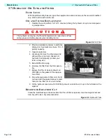
Страница 31: ...aulic fluid properly contact your local oil recycler 5 Reinstall the drain plug 6 Unscrew the filter from the filter assem bly 7 Apply a thin film of clean hydraulic oil ISO 46 to the gasket of the re...

Страница 32: ...ockwise two full turns 5 Operate telescope in function switch at lower controls and keep it activated 6 Slowly turn the main relief valve adjusting screw clockwise until the pressure gauge reads 155 B...

Страница 33: ...l turns 5 Operate slew function from lower controls and rotate elevating assembly through approx 180o until the slew stop prevents further rotation 6 Slowly turn the cross line relief valve adjusting...

Страница 34: ...ompressed air 2 Inspect the manifold for cracks thread damage and scoring where the O rings seal against internal and external surfaces 3 Wash and dry each component and check for thread damage torn o...

Страница 35: ...LE 8 FITTING 3 8 1 4 MALE MALE 9 FITTING 3 8 1 4 MALE MALE 10 Blanking Cap 11 Blanking Cap 12 FITTING 3 8 1 4 MALE MALE 13 FITTING 3 8 1 4 MALE MALE 14 Test Port 15 CROSS LINE RELIEF VALVE SLEW 16 CRO...

Страница 36: ...th clean compressed air 2 Inspect the manifold for cracks thread damage and scoring where the O rings seal against internal and external surfaces 3 Wash and dry each component and check for thread dam...

Страница 37: ...FITTING 1 4 1 4 MALE MALE BULKHEAD 4 FITTING 1 4 1 4 MALE MALE BULKHEAD 5 FITTING 1 4 1 4 MALE MALE 6 FITTING 1 4 1 4 MALE MALE 7 FITTING 1 4 1 4 MALE MALE 8 FITTING 1 4 1 4 MALE MALE 9 FITTING 1 2 1...

Страница 38: ...age to be held in position by suitable support slings or by another person REMOVAL 1 Disconnect both hoses and plug ends to avoid excessive oil spillage Note which hose goes to which port 2 Remove loc...

Страница 39: ...o place and insert the body end pin in through the cylinder and Second Post Anchors Note take care in aligning the pin in the holes so that the pin can be pushed in by hand If the pin and holes are no...

Страница 40: ...alling Tele Cylinder check cylinder pins and bearings for wear and replace if necessary 1 Lift the cylinder into place and slide it into the back end of the Inner Boom 2 Insert a metal bar e g a screw...

Страница 41: ...attach a sling to the second post and to an overhead crane 3 Disconnect the two hoses from the cylinder body and plug Note which hose goes to which port 4 Remove lock plate securing bolt and spring wa...

Страница 42: ...hed in by hand If the pin and holes are not properly aligned and the pin is forced in the bushings will be damaged 2 Line the Lower Boom Anchor holes up with the cylinder rod hole and insert the rod e...

Страница 43: ...attach a sling to the Upper Boom platform end and to an overhead crane 3 Disconnect the two hoses from the cylinder body and plug Note which hose goes to which port 4 Remove lock plate securing bolt a...

Страница 44: ...end This should be used to raise and lower the Upper Boom 3 Slide both locking plates into the groves on the pins and secure with the bolts and washers 4 Reconnect the hoses to their correct ports 5...

Страница 45: ...valve cartridges and overcentre valve cartridges from the cylinder blocks 2 Bend up tab on tab washer if applicable 3 Unscrew end cap and remove from cylinder body with rod and piston 4 Unscrew the pi...

Страница 46: ...and grub screw where applicable 4 Lubricate the entire assembly s seals and slide the piston into the cylinder body 5 Screw end cap onto end of cylinder body 6 Bend down tab on tab washer 7 Insert al...

Страница 47: ...shaft running free the ammeter should read less than 20 of the nameplate full load current If the motor meets the above conditions then it can be assumed the original problem is external to the motor...

Страница 48: ...115 122 950 1050 107 119 16 130 140 176 190 130 140 176 190 1300 1368 147 155 SAE J429 Grade 5 SAE J429 Grade 8 SAE J429 Grade 5 SAE J429 Grade 8 Nominal Thread Size Clamp Load Tightening Torque Clam...

Страница 49: ...82 2 909 4 27 46 435 617 3 84 8 64 235 853 4 1138 1 75 069 997 2 1329 8 30 56 753 837 9 1117 4 78 509 1159 4 1545 2 91 751 1354 9 1807 0 33 70 208 1140 3 1520 1 97 121 1576 9 2102 8 113 503 1843 9 245...

Страница 50: ...re Daily tightened Check drop bar on cage entrance Daily COMPONENT INSPECTION OR SERVICES INTERVAL Y N R Signature of Service Engineer _____________________________ Slew Grease slew gear 50h 30d Syste...

Страница 51: ...Page 3 30 Maintenance 3 19 Torque Specifications TL50 Service Parts NOTES...

Страница 52: ...lp in diagnosing and repair of the machine GENERAL PROCEDURE Thoroughly study hydraulic and electronic schematics in Section 5 Check for loose connections and short circuits Check repair replace each...

Страница 53: ...at all functions are operating correctly and that the machine is performing to specified values SPECIAL TOOLS Following is a list of tools which may be required to perform certain maintenance procedur...

Страница 54: ...nctionality of controller Replace if faulty upper controls 4 Blown control fuse Check 7A circuit contrrol fuse Replace if blown 5 Battery level low Check Battery Voltage Charge if necessary Check for...

Страница 55: ...stop button If the fault code is still displayed you may have a faulty upper or lower control box consult the error code list to identify the problem component and replace if necessary For fault code...

Страница 56: ...rm Telescope Switch ON at power up 27 Platform Lower Boom Switch ON at power up 28 Platform Upper Boom Switch ON at power up 29 Platform Joystick Enable Switch ON at power up 31 Platform Joystick not...

Страница 57: ...l fault 63 Level Platform Cage Down Coil fault 66 Drive Forward Coil fault 67 Drive Reverse Coil fault 68 Low Battery fault 71 Rotate Platform Cage Left Coil fault 72 Rotate Platform Cage Right Coil f...

Страница 58: ...TICS 5 1 INTRODUCTION This section contains electrical and hydraulic power schematics and associated information for maintenance purposes CONTENTS Schematic J1 Harness 5 2 Schematic J2 Harness 5 3 Ele...

Страница 59: ...Page 5 2 Schematics 5 1 Introduction TL50 Service Parts...

Страница 60: ...Page 5 3 Schematics 5 1 Introduction TL50 Service Parts...

Страница 61: ...Page 5 4 Schematics 5 1 Introduction TL50 Service Parts...

Страница 62: ...Page 5 5 Schematics 5 1 Introduction TL50 Service Parts...

Страница 63: ...Page 5 6 Schematics 5 1 Introduction TL50 Service Parts Notes...

Страница 64: ...Playform Assembly Rotator 6 10 Outrigger Assembly 6 12 Power Control Module Assembly 6 13 Hydraulic Manifold Assembly Main 6 14 Hydraulic Manifold Assembly Outrigger 6 15 Tow Hitch Assembly 6 16 Plat...

Страница 65: ...001 000 CHASSIS ASSEMBLY 1 2 503002 000 BOOMS POSTS ASSEMBLY 1 3 503003 000 PLATFORM ASSEMBLY 1 4 503004 000 POWER CONTROL MODULE ASSEMBLY 1 5 503007 000 OUTRIGGER ASSEMBLY 4 6 502543 000 PLATFORM CON...

Страница 66: ...Page 6 3 Illustrated Parts Breakdown General Assembly TL50 Service Parts 1 1 2 3 4 5 6 7...

Страница 67: ...2 058071 000 TYRE ONLY 2 058070 000 RIM ONLY 2 057474 000 WHEEL NUT 10 057471 000 WHEEL STUD 10 11 500310 000 MUDGUARD BRACKET 2 12 503016 000 BOOM REST 1 13 503143 000 BRAKE ROD SUPPORT 1 14 503144...

Страница 68: ...Page 6 5 Illustrated Parts Breakdown Chassis Assembly TL50 Service Parts Chassis Assembly 503001 000...

Страница 69: ...2nd POST 1 22 058066 008 PIVOT PIN UPPER LIFT ROD UPPER BOOM 1 23 058065 006 PIVOT PIN 2nd POST MASTER CYL BODY 1 24 058065 001 PIVOT PIN MASTER CYL ROD UPPER BOOM 1 25 058055 007 PIVOT PIN 2nd POST U...

Страница 70: ...Page 6 7 Illustrated Parts Breakdown Booms Posts Assembly TL50 Service Parts 44 45...

Страница 71: ...GE RAIL ASSEMBLY 1 6 057190 000 TAILBOARD ASSEMBLY EURO 1 057190 001 TAILBOARD ASSEMBLY USA 1 057190 002 TAILBOARD ASSEMBLY UK IRELAND 1 7 058244 000 TAILBOARD GUARD mesh 1 8 057347 000 LADDER 1 9 503...

Страница 72: ...Page 6 9 Illustrated Parts Breakdown Platform Assembly Standard TL50 Service Parts...

Страница 73: ...URO 1 057190 001 TAILBOARD ASSEMBLY USA 1 057190 002 TAILBOARD ASSEMBLY UK IRELAND 1 7 058244 000 TAILBOARD GUARD mesh 1 8 057347 000 LADDER 1 9 056066 012 M12 NYLOCK NUT 2 10 056069 012 M12 WASHER 4...

Страница 74: ...Page 6 11 Illustrated Parts Breakdown Platform Assembly Rotator TL50 Service Parts...

Страница 75: ...iption QTY 1 500060 000 PIVOT PIN FOOTPAD LARGE 1 2 500061 000 PIVOT PIN FOOTPAD SMALL 1 3 503278 000 FOOTPAD 1 4 503277 000 OUTRIGGER ARM 1 5 058056 000 LOCKPLATE 2 6 057046 000 BUSHING 2 7 058055 00...

Страница 76: ...PLATE 3 4 057082 000 CLAMP BOLT 3 5 501619 000 BATTERY CABLE CONNECTOR HANDLE 1 6 503049 000 MODULE COVER 1 7 503299 000 HINGE 2 8 504536 000 PUMP MOTOR UNIT 1 9 503183 000 GAS SPRING 1 10 503184 000...

Страница 77: ...MALE FITTING 1 2 X 1 2 1 2 058722 000 RELIEF VALVE 3 3 057122 000 MALE MALE FITTING 3 8 X 3 8 3 4 057121 000 MALE MALE FITTING 3 8 X 1 4 8 5 500261 002 HANDPUMP 1 6 503351 000 SOLENOID VALVE SLEW 1 7...

Страница 78: ...arts Hydraulic Block Outrigger 058180 010 Item Part Description QTY 1 058723 000 SOLENOID VALVE COILS 4 2 058180 001 SOLENOID VALVE COIL 1 3 057123 000 FITTING MALE MALE 3 8 X 1 2 1 4 057122 000 FITTI...

Страница 79: ...MBLY 1 2 057486 000 SAFETY CABLE 1 3 058794 000 SPRING BACK ASSEMBLY 1 4 058790 000 GAITER 1 5 058791 000 COUPLING HEAD 1 6 501828 000 MOUNTING DUAL JOCKEY WHEEL 1 7 501042 001 BRACKET JOCKEY WHEEL 1...

Страница 80: ...Controls Assembly Item Part Description QTY 1 502453 000 CIRCUIT BOARD 1 2 501866 000 KEY SWITCH 1 3 501867 000 EMERGENCY STOP BUTTON 1 4 503291 000 DECAL 1 5 501881 000 ENCLOSURE 1 6 501882 000 JOYS...

Страница 81: ...Y STOP BUTTON 1 066805 011 CONTACT BLOCK EM STOP 1 2 502560 000 SOCKET 1 3 503288 000 DECAL 1 4 501866 000 KEY SWITCH 501866 001 FOR THE KEY ALONE 1 5 502539 000 ANALOG ROCKER 1 6 502451 000 ECU 1 7 5...

Страница 82: ...er Lift Cylinder Assembly TL50 Service Parts Lower Lift Cylinder Assembly 503153 000 Item Part Description QTY 1 058887 000 EMERGENCY DOWN VALVE 1 2 058728 000 OVERCENTRE VALVE 1 3 503153 010 SEAL KIT...

Страница 83: ...per Lift Cylinder Assembly TL50 Service Parts Upper Lift Cylinder Assembly 058731 000 Item Part Description QTY 1 058887 000 EMERGENCY DOWN VALVE 1 2 058728 000 OVERCENTRE VALVE 1 3 058731 010 SEAL KI...

Страница 84: ...escopic Cylinder Assembly TL50 Service Parts Telescopic Cylinder Assembly 503112 000 Item Part Description QTY 1 058728 000 OVERCENTRE VALVE 1 2 058714 000 SINGLE PO CHECK VALVE 1 3 503112 010 SEAL KI...

Страница 85: ...ice Parts Master Slave Levelling Cylinder Assembly MASTER 058734 000 SLAVE 058735 000 NOTE THE SAME SEAL KIT 058750 000 IS USED FOR BOTH CYLINDERS 058734 000 058735 000 Item Part Description QTY 1 058...

Страница 86: ...Outrigger Cylinder Assembly TL50 Service Parts Outrigger Cylinder Assembly 058988 002 Item Part Description QTY 1 058925 000 SINGLE PO CHECK VALVE 1 2 058728 000 OVERCENTRE VALVE 1 058988 010 SEAL KIT...

Страница 87: ...ic Tank Assembly TL50 Service Parts Hydraulic Tank Assembly 503020 000 Item Part Description QTY 1 502275 000 FILTER RETURN 1 2 503169 000 FITTING MALE MALE 3 4 X 1 2 1 3 057534 000 FILLER CAP 1 4 058...

Страница 88: ...Page 6 25 Illustrated Parts Breakdown Hydraulic Tank Assembly TL50 Service Parts...

Страница 89: ...CT 1 14 502552 000 HARNESS CHARGER DISCONNECT LINE CON4 1 15 502553 000 HARNESS CHARGER DISCONNECT BATT 1 16 502554 000 HARNESS CHARGER DISCONNECT LINE CON2 1 17 502555 000 LINE CONTACTOR 3 FUSE 1 18...

Страница 90: ...Page 6 27 Illustrated Parts Breakdown Electrical Assembly TL50 Service Parts...

Страница 91: ...IGGER 1 1 N I A M K C O L B D L O F I N A M 1 0 0 6 5 0 3 0 5 0 1 2 1 1 2 2 1 1 M F M 2 1 E C E I P T 0 0 0 3 6 5 2 0 5 4 1 2 6 1 2 7 1 2 E S O H 8 1 1 0 2 21 510256 000 HOSE 1 2 M1T B90 400 B90 1 22...

Страница 92: ...Page 6 29 Illustrated Parts Breakdown Hydraulic Assembly TL50 Service Parts...

Страница 93: ...017 000 503291 000 503177 000 503288 000 057421 000 ITEM 19 20 6 25 27 26 22 23 24 20 21 17 18 14 15 16 11 13 12 8 10 9 7 6 5 4 3 2 1 5 QTY DESCRIPTION HAND PUMP OPERATION OUTRIGGER LOWERED BOOM LOCK...

Страница 94: ...Page 6 31 Illustrated Parts Breakdown Decal Assembly TL50 Service Parts...

Страница 95: ...Page 6 32 Illustrated Parts Breakdown Decal Assembly TL50 Service Parts...

Страница 96: ...Technician s Print TL50 W ork Platform Electrical Schematic...

Страница 97: ...Technician s Print TL50 W ork Platform Harness Schematic...

Страница 98: ......

Страница 99: ...443 6600 FAX 1 559 268 2433 www upright com PN 503502 000 Europe TEL 44 0 845 1550 058 FAX 44 0 195 2299 948 Local Distributor Lokaler Vertiebsh ndler Distributeur local El Distribuidor local Il Distr...

Отзывы: