background image

2.4 Safety Modes

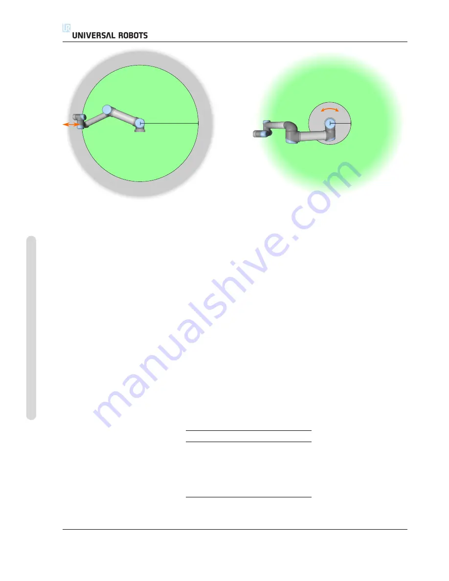
450 mm

200 mm

Figure 2.1: Certain areas of the workspace should receive attention regarding pinching hazards, due to the
physical properties of the robot arm. One area is defined for radial motions, when the wrist 1 joint is at a
distance of at least 450 mm from the base of the robot. The other area is within 200 mm of the base of the
robot, when moving in the tangential direction.

Using a plane to trigger Reduced mode:

When the robot moves from the Reduced mode side of the

trigger plane, back to the Normal mode side, there is a 20mm area around the trigger plane where

both Normal and Reduced mode limits are allowed. It prevents the safety mode from flickering if

the robot is right at the limit.

Using an input to trigger Reduced mode:

When an input is used (to either start or stop Reduced

mode), up to 500ms can elapse before the new mode limit values are applied. This could happen

either when changing Reduced mode to Normal mode OR changing Normal mode to Reduced

mode. It allows the robot to adapt e.g. the speed to the new safety limits.

Recovery Mode

When a safety limit is violated, the safety system must be restarted. If the system

is outside a safety limit at start-up (e.g. outside a joint position limit), the special

Recovery

mode is

entered. In Recovery mode it is not possible to run programs for the robot, but the robot arm can

be manually moved back within limits either by using

Freedrive

mode or by using the Move tab in

PolyScope (see part II “PolyScope Manual”). The safety limits of

Recovery

mode are:

Limiting Safety Function

Limit

Joint speed

30

/

s

TCP speed

250

mm

/

s

TCP force

100 N

Momentum

10

kg m

/

s

Power

80 W

The safety system issues a Stop Category 0 if a violation of these limits appears.

UR3

/

CB3

I-16

Version 3.10

Cop

yr

ight

©

2009–2019

b

y

Univ

ersal

Robots

A/S

.

All

rights

reser

v

ed.

Содержание UR3/CB3

Страница 1: ...Universal Robots UR3 CB3 Original instructions en US version...

Страница 2: ......

Страница 3: ...Universal Robots UR3 CB3 Euromap67 Version 3 10 Original instructions en US Version...

Страница 4: ...t notice and should not be construed as a commitment by Universal Robots A S This manual is periodically reviewed and revised Universal Robots A S assumes no responsibility for any errors or omissions...

Страница 5: ...rgency Stop I 10 1 9 Movement With and Without Drive Power I 10 2 Safety related Functions and Interfaces I 13 2 1 Introduction I 13 2 2 Stopping times of the Safety System I 14 2 3 Limiting Safety re...

Страница 6: ...air I 49 6 1 Safety Instructions I 49 7 Disposal and Environment I 51 8 Certifications I 53 8 1 Third Party Certification I 53 8 2 Supplier Third Party Certification I 54 8 3 Manufacturer Test Certifi...

Страница 7: ...t Limits II 11 10 12 Boundaries II 12 10 12 1 Selecting a boundary to configure II 13 10 12 2 3D visualization II 14 10 12 3 Safety plane configuration II 14 10 12 4 Tool Boundary configuration II 18...

Страница 8: ...5 13 7 Installation Mounting II 46 13 8 Installation I O Setup II 47 13 8 1 I O Signal Type II 48 13 8 2 Assigning User defined Names II 48 13 8 3 I O Actions and I O Tab Control II 48 13 9 Installati...

Страница 9: ...til II 85 14 11 Command Wait II 87 14 12 Command Set II 88 14 13 Command Popup II 89 14 14 Command Halt II 90 14 15 Command Comment II 91 14 16 Command Folder II 92 14 17 Command Loop II 93 14 18 Comm...

Страница 10: ...III 7 17 3 Mounting the robot and tool III 8 17 4 Using the robot without an IMM III 8 17 5 EUROMAP 12 to EUROMAP 67 conversion III 8 18 GUI III 11 18 1 EUROMAP 67 program template III 11 18 2 I O ov...

Страница 11: ...Electrical characteristics III 27 20 1 MAF light guard interface III 27 20 2 Emergency stop safety devices and MAF signals III 27 20 3 Digital Inputs III 28 20 4 Digital Outputs III 28 Glossary III 2...

Страница 12: ...UR3 CB3 x Version 3 10 Copyright 2009 2019 by Universal Robots A S All rights reserved...

Страница 13: ...program the robot to move the tool along a desired trajectory What Do the Boxes Contain When you order a robot you receive two boxes One contains the Robot Arm the other contains Control Box with Teac...

Страница 14: ...Find More Information The support website http www universal robots com support contains the following Other language versions of this manual PolyScope Manual The Service Manual with instructions for...

Страница 15: ...Part I Hardware Installation Manual...

Страница 16: ......

Страница 17: ...or any other equipment due to programming errors or malfunctioning of the robot 1 2 Validity and Responsibility The information in this manual does not cover designing installing and operating a compl...

Страница 18: ...er levels used throughout this manual The same warning signs are used on the product DANGER This indicates an imminently hazardous electrical situation which if not avoided could result in death or se...

Страница 19: ...ome general warnings and cautions that can be repeated or explained in different parts of this manual Other warnings and cautions are present throughout this manual DANGER You must install the robot a...

Страница 20: ...ding error codes on the log screen and contact your supplier 7 Do not connect any safety equipment to standard I O Use safety related I O only 8 Make sure to use the correct installation settings e g...

Страница 21: ...ewest version of all rele vant service manuals 16 If the robot is purchased with an extra module e g euromap67 interface then look up that module in the respective manual WARNING 1 The robot and its c...

Страница 22: ...ng parameters 1 7 Risk Assessment One of the most important things that an integrator needs to do is to perform a risk assessment In many countries this is required by law The robot itself is partly c...

Страница 23: ...iguration by using password protection A collaborative robot application risk assessment for contacts that are intentional and or due to reasonably foreseeable misuse is required and must address Seve...

Страница 24: ...7 5 5 see section 5 3 2 1 9 Movement With and Without Drive Power In the unlikely event of an emergency situation where one or more robot joints need to be moved and robot power is either not possible...

Страница 25: ...1 9 Movement With and Without Drive Power Version 3 10 Copyright 2009 2019 by Universal Robots A S All rights reserved I 11 UR3 CB3...

Страница 26: ...1 9 Movement With and Without Drive Power UR3 CB3 I 12 Version 3 10 Copyright 2009 2019 by Universal Robots A S All rights reserved...

Страница 27: ...face NOTE 1 Use and configuration of safety related functions and interfaces must be done according to the risk assessment that the integra tor conducts for a specific robot application see section 1...

Страница 28: ...ke place immediately after the stop the maximum stopping times must be considered The measurements are conducted with the following configuration of the robot Extension 100 the robot arm is fully exte...

Страница 29: ...e arm when the tool is close to the base and moving tangential around the base can cause high forces but also at low speeds Pinching haz ards can be avoided for instance by removing obstacles in these...

Страница 30: ...mode up to 500ms can elapse before the new mode limit values are applied This could happen either when changing Reduced mode to Normal mode OR changing Normal mode to Reduced mode It allows the robot...

Страница 31: ...ocks this signal will not be forwarded to other machines through the System emergency stop output Safeguard Stop Dedicated Input Performs a Stop Category 2 Safeguard Reset Configurable Input Resumes t...

Страница 32: ...ransition to Reduced mode triggered by the reduced mode input is monitored as follows 1 The safety system accepts both Normal and Reduced mode limit sets for 500 ms after the reduced mode input is tri...

Страница 33: ...ing due to an emergency stop or safeguard stop Otherwise it will be logic low Reduced Mode Logic low when the safety system is in Reduced mode Not Reduced Mode The Reduced mode output negated If a saf...

Страница 34: ...2 5 Safety related Electrical Interfaces UR3 CB3 I 20 Version 3 10 Copyright 2009 2019 by Universal Robots A S All rights reserved...

Страница 35: ...d at the base of the robot The controller box shall be lifted by the handle WARNING 1 Make sure not to overload your back or other bodyparts when the equipment is lifted Use proper lifting equipment A...

Страница 36: ...UR3 CB3 I 22 Version 3 10 Copyright 2009 2019 by Universal Robots A S All rights reserved...

Страница 37: ...ng it difficult to conduct a risk assessment Front Tilted 4 3 Mounting Robot Arm The robot arm is mounted using four M6 bolts using the four 6 6 mm holes on the base It is recommended to tighten these...

Страница 38: ...a tool to the robot The M6 bolts need to be tightened with 9 N m If very accurate repositioning of the tool is desired the 6 hole is provided for use with a pin Figure 4 2 shows where to drill holes...

Страница 39: ...4 3 Mounting Figure 4 1 Holes for mounting the robot Use four M6 bolts All measurements are in mm Version 3 10 Copyright 2009 2019 by Universal Robots A S All rights reserved I 25 UR3 CB3...

Страница 40: ...he control box teach pendant and cables do not come into contact with liquids A wet control box could cause death 2 The control box and teach pendant must not be exposed to dusty or wet environments t...

Страница 41: ...vity offset is defined as the distance between the center of the tool output flange and the center of gravity 0 100 200 300 400 1 2 3 4 Center of gravity offset mm Payload kg Figure 4 3 Relationship b...

Страница 42: ...4 4 Maximum Payload UR3 CB3 I 28 Version 3 10 Copyright 2009 2019 by Universal Robots A S All rights reserved...

Страница 43: ...ns The following warnings and cautions must be observed when a robot application is designed and installed The warnings and cautions also apply for service work DANGER 1 Never connect safety signals t...

Страница 44: ...nstalling interface cables to the robot I O The metal plate in the bottom is intended for interface ca bles and connectors Remove the plate before drilling the holes Make sure that all shavings are re...

Страница 45: ...of the different colors must be observed see below Yellow with red text Dedicated safety signals Yellow with black text Configurable for safety Gray with black text General purpose digital I O Green...

Страница 46: ...GND Voltage 23 24 25 V PWR GND Current 0 2 A External 24V input requirements 24V 0V Voltage 20 24 29 V 24V 0V Current 0 6 A The digital I O are constructed in compliance with IEC 61131 2 The electrica...

Страница 47: ...ty inputs are the Robot Emergency Stop and the Safeguard Stop The Robot Emergency Stop input is for emergency stop equipment only The Safeguard Stop input is for all kinds of safety related protective...

Страница 48: ...unction could be overridden 5 3 2 1 Default safety configuration The robot is shipped with a default configuration which enables operation without any additional safety equipment see illustration belo...

Страница 49: ...24V CI0 Configurable Inputs 24V CI5 24V CI6 24V CI7 24V CI4 0V CO1 0V CO2 0V CO3 0V CO0 Configurable Outputs 0V CO5 0V CO6 0V CO7 0V CO4 A B If more than two UR robots or other machines need to be co...

Страница 50: ...ain a reset outside the safety perimeter is required The reset button must be a two channel type In this example the I O configured for reset is CI0 CI1 see below 24V EI1 24V SI0 24V SI1 24V EI0 Safet...

Страница 51: ...pneumatic relays directly or for communication with other PLC systems All digital outputs can be disabled automatically when program execution is stopped see more in part II In this mode the output i...

Страница 52: ...igital Outputs 0V DO5 0V DO6 0V DO7 0V DO4 A B 5 3 6 General purpose analog I O The analog I O interface is the green terminal It can be used to set or measure voltage 0 10V or current 4 20mA from and...

Страница 53: ...Analog output in voltage mode AOx AG Voltage 0 10 V AOx AG Current 20 20 mA AOx AG Resistance 1 ohm AOx AG Resolution 12 bit The following examples show how to use the analog I O 5 3 6 1 Using an ana...

Страница 54: ...The on and off inputs are intended for short time activation only The on input works in the same way as the power button Always use the off input for remote off control as this signal allows the cont...

Страница 55: ...end of the robot there is a small connector with eight pins see illustration below This connector provides power and control signals for grippers and sensors used on a specific robot tool The followin...

Страница 56: ...cribe the different I O s of the tool DANGER 1 Connect tools and grippers such that an interruption of power does not create any hazards e g a work piece falling out of the tool 2 Take care when using...

Страница 57: ...tput voltage at the I O tab Keep in mind that there is voltage between the POWER connection and the shield ground even when the load is turned off TO0 POWER Note It is highly recommended to use a prot...

Страница 58: ...amples of how to use analog inputs are shown in the following subsections CAUTION 1 Analog inputs are not protected against over voltage in current mode Overrating the limit in the electrical specific...

Страница 59: ...nsion modules See more in part II Remote access and control The electrical specifications are shown below Parameter Min Typ Max Unit Communication speed 10 1000 Mb s 5 6 Mains connection The mains cab...

Страница 60: ...d ing of all equipment in the system The grounding conductor shall have at least the current rating of the highest current in the system 2 Make sure that the input power to the controller box is prote...

Страница 61: ...tion CAUTION 1 Do not disconnect the robot cable when the robot arm is turned on 2 Do not extend or modify the original cable Version 3 10 Copyright 2009 2019 by Universal Robots A S All rights reserv...

Страница 62: ...5 7 Robot connection UR3 CB3 I 48 Version 3 10 Copyright 2009 2019 by Universal Robots A S All rights reserved...

Страница 63: ...ent of a fault to return the system to an operational state Repair work includes troubleshoot ing in addition to the actual repair itself When working on the robot arm or control box you must observe...

Страница 64: ...epair period 2 Check the earth connection before re powering the system 3 Observe ESD regulations when parts of the robot arm or control box are disassembled 4 Avoid disassembling the power supplies i...

Страница 65: ...for disposal and handling of electronic waste of UR robots sold on the Danish market is prepaid to DPA system by Universal Robots A S Importers in countries covered by the European WEEE Directive 201...

Страница 66: ...UR3 CB3 I 52 Version 3 10 Copyright 2009 2019 by Universal Robots A S All rights reserved...

Страница 67: ...hinery directive 2006 42 EC in EU You can find a copy of the TU V Rheinland certificate in appendix B DELTA UR robots are performance tested by DELTA You can find electromagnetic compatibility EMC and...

Страница 68: ...nery Directive MD According to the Machinery Directive 2006 42 EC UR robots are partly completed machinery as such a CE mark is not affixed Note If the UR robot is used in a pesticide application you...

Страница 69: ...aims resulting out of or in connection with the device shall be excluded from this Warranty Nothing in this Warranty shall attempt to limit or exclude a Customer s Statutory Rights nor the manufacture...

Страница 70: ...erefore reserves the right to upgrade the product without prior warning Universal Robots takes every care that the contents of this manual are precise and correct but takes no responsibility for any e...

Страница 71: ...zontally Speed 100 the general speed of the robot is set to 100 and the movement is performed at a joint speed of 183 s Payload maximum payload handled by the robot attached to the TCP 3 kg The test o...

Страница 72: ...A 1 Stop Category 0 stopping distances and times UR3 CB3 I 58 Version 3 10 Copyright 2009 2019 by Universal Robots A S All rights reserved...

Страница 73: ...to a final com plete machine robot system cell or application which conforms with the provisions of the Machinery Directive and other ap plicable Directives It is declared that the above products for...

Страница 74: ...529 1991 A2 2013 Certificate 4478014097602 Reference to Other Technical Standards and Specifications Used I ISO 9409 1 20047 III IEC 60068 2 27 2008 II IEC 61784 3 2010 SIL2 I ISO TS 15066 as applicab...

Страница 75: ...B 2 Safety System Certificate B 2 Safety System Certificate Version 3 10 Copyright 2009 2019 by Universal Robots A S All rights reserved I 61 UR3 CB3...

Страница 76: ...B 3 TUV Rheinland B 3 TUV Rheinland UR3 CB3 I 62 Version 3 10 Copyright 2009 2019 by Universal Robots A S All rights reserved...

Страница 77: ...B 4 China RoHS B 4 China RoHS Version 3 10 Copyright 2009 2019 by Universal Robots A S All rights reserved I 63 UR3 CB3...

Страница 78: ...B 5 KCC Safety B 5 KCC Safety UR3 CB3 I 64 Version 3 10 Copyright 2009 2019 by Universal Robots A S All rights reserved...

Страница 79: ...Robot system UR3 including its Robot Arm Control Box and Teach Pendant has been tested according to the below listed standards The test results are given in the DELTA report listed above The tests wer...

Страница 80: ...hority National Telecom Administration part of the Energy Agency in Denmark to carry out tasks referred to in Annex III of the European Council EMC Directive The attestation of conformity is in accord...

Страница 81: ...ing ISO 14644 1 The certificate is limited to the particulate cleanliness The product was tested according to VDI 2083 Part 9 1 in August 2016 The implementation of the testing and certification is ca...

Страница 82: ...The certificate is limited to the particulate cleanliness The product was tested according to VDI 2083 Part 9 1 in August 2016 The implementation of the testing and certification is carried out by T V...

Страница 83: ...European Norm TS Technical Specification TR Technical Report ANSI American National Standards Institute RIA Robotic Industries Association CSA Canadian Standards Association Conformity with the follow...

Страница 84: ...traditionally safe guarded by fences and light curtains UR robots are designed with force and power limiting enabled at all times Therefore some concepts are clarified and explained below If a UR robo...

Страница 85: ...for industrial robots Collaborative operation This is a Technical Specification TS not a standard The purpose of a TS is to present a set of immature requirements to see if they are useful for a given...

Страница 86: ...tandards ensures that the UR robots perform well in industrial environments and that they do not disturb other equipment IEC 61326 3 1 2008 EN 61326 3 1 2008 Electrical equipment for measurement contr...

Страница 87: ...rements in this standard IEC 60529 2013 EN 60529 A2 2013 Degrees of protection provided by enclosures IP Code This standard defines enclosure ratings regarding protection against dust and water UR rob...

Страница 88: ...defined in the Hardware Installation Manual IEC 60068 2 1 2007 IEC 60068 2 2 2007 IEC 60068 2 27 2008 IEC 60068 2 64 2008 EN 60068 2 1 2007 EN 60068 2 2 2007 EN 60068 2 27 2009 EN 60068 2 64 2008 Env...

Страница 89: ...Principles requirements and tests Part 5 Comprehensive method for determining clearances and creepage distances equal to or less than 2 mm The electrical circuitry of UR robots is designed in complia...

Страница 90: ...UR3 CB3 I 76 Version 3 10 Copyright 2009 2019 by Universal Robots A S All rights reserved...

Страница 91: ...EEE 802 3u 100BASE T Ethernet socket modbus TCP EtherNet IP Adapter Profinet Programming PolyScope graphical user interface on 12 touchscreen Noise 70 dB A IP classification IP54 Cleanroom classificat...

Страница 92: ...UR3 CB3 I 78 Version 3 10 Copyright 2009 2019 by Universal Robots A S All rights reserved...

Страница 93: ...E Safety Functions Tables E 1 Table 1 Version 3 10 Copyright 2009 2019 by Universal Robots A S All rights reserved I 79 UR3 CB3...

Страница 94: ...E 1 Table 1 UR3 CB3 I 80 Version 3 10 Copyright 2009 2019 by Universal Robots A S All rights reserved...

Страница 95: ...E 1 Table 1 Version 3 10 Copyright 2009 2019 by Universal Robots A S All rights reserved I 81 UR3 CB3...

Страница 96: ...E 2 Table 2 E 2 Table 2 UR3 CB3 I 82 Version 3 10 Copyright 2009 2019 by Universal Robots A S All rights reserved...

Страница 97: ...E 2 Table 2 Version 3 10 Copyright 2009 2019 by Universal Robots A S All rights reserved I 83 UR3 CB3...

Страница 98: ...E 2 Table 2 UR3 CB3 I 84 Version 3 10 Copyright 2009 2019 by Universal Robots A S All rights reserved...

Страница 99: ...Part II PolyScope Manual...

Страница 100: ......

Страница 101: ...up and teaching must be applied according to the risk assessment conducted by the inte grator and before the robot arm is powered on for the first time 3 All safety configuration settings accessible...

Страница 102: ...The joint speed limits define the maximum angular velocity of individual joints and serve to further limit the speed of the robot arm The joint position limits define the allowed position range of ind...

Страница 103: ...defined below Configuration Synchronized Shows the GUI installation is identical to the currently applied safety configuration No changes have been made Configuration Altered Shows the GUI installati...

Страница 104: ...or example the general speed tolerance is 150mm s This means that if the user configures a 250mm s speed limit then the maximum operational speed will be 250 150 100mm s Safety tolerances prevent safe...

Страница 105: ...ack within the limits The subtabs of the Safety Configuration screen enable the user to define separate sets of safety limits for Normal and Reduced mode For the tool and joints Reduced mode limits re...

Страница 106: ...rect safety password see 15 3 is entered in the white text field at the bottom of the screen and the Unlock button is pressed The screen can be locked again by clicking the Lock button The Safety tab...

Страница 107: ...nt Speed A limit for the maximum linear speed of the robot TCP Momentum A limit for the maximum momentum of the robot arm There are two means available for configuring the general safety limits within...

Страница 108: ...e advanced general limits screen Advanced Settings Here each of the general limits described in 10 10 can be modified independently of the others This is done by tapping the corresponding text field a...

Страница 109: ...her parts of the robot arm may move faster than the defined value Switching to Basic Settings Pressing the Basic Settings button switches back to the basic general limits screen and all general limits...

Страница 110: ...xceed the entered value without tolerance the safety system performs a Stop Category 0 Position Range This screen defines the position range for each joint This is done by tapping the corresponding te...

Страница 111: ...ailable When in Freedrive mode see 13 1 5 and the current position of the robot TCP is close to a safety plane or the deviation of the orientation of the robot tool from the desired orientation is clo...

Страница 112: ...ch indicates the side of the plane on which the robot TCP is allowed to be positioned Trigger planes are displayed in blue and green A small arrow illustrates the side of the plane that does not trigg...

Страница 113: ...e plane normal indicates the side of the plane that does not trigger transition into Reduced mode It should be noted that when the safety plane has been configured by selecting a feature the posi tion...

Страница 114: ...and entering a value Entering in a positive value increases the allowed workspace of the robot by moving the plane in the oppo site direction of the plane normal while entering a negative value decrea...

Страница 115: ...longer active and the Reduced mode limit set is enforced When a transition from Reduced to Normal mode is caused by passing through a Trigger Reduced mode plane a transition from the Reduced mode limi...

Страница 116: ...using a feature see 13 12 from the current robot installation The z axis of the selected feature will be used as the desired tool orientation vector for this limit Use the drop down box in the lower l...

Страница 117: ...Normal Reduced When the safety system is either in Normal or Re duced mode the tool boundary limit is active The selected safety mode is indicated by an icon in the corresponding entry in the Safety B...

Страница 118: ...gnals Note Applying a safety function to a set of pins will override any I O actions specified for pins in the I O Setup see 13 8 10 13 1 Input Signals For input signals the following Safety functions...

Страница 119: ...onal Mode These allow for using a 3 position enabling device as an additional protective measure during setup and programming of the robot With the Three Position Enabling Device input configured the...

Страница 120: ...ven when the safety system has been triggered into an Emergency Stopped state by the Robot Emergency Stop input or Emergency Stop Button To avoid deadlocks if the Emergency Stopped state is triggered...

Страница 121: ...l is logic low Reduced Mode Sends a low signal when the robot arm is placed in Reduced mode or if the safety input is configured with a Reduced Mode input and the signal is currently low Otherwise the...

Страница 122: ...10 13 Safety I O CB3 II 24 Version 3 10 Copyright 2009 2019 by Universal Robots A S All rights reserved...

Страница 123: ...on which must be read and understood by the integra tor of UR robots before the robot is powered on for the first time 2 The integrator must set the safety configuration parameters de fined by the ris...

Страница 124: ...on the touch screen After about one minute a few buttons appear on the screen and a popup guides the user to the initialization screen see 11 5 To shut down the control box press the green power butto...

Страница 125: ...he mounting detected based on sensor data does not match the selected mounting 11 Touch the Start button on the touch screen The robot now makes a sound and moves a little while releasing the brakes 1...

Страница 126: ...button while pulling the robot arm 13 Press OK 14 Your program is ready The robot will move between the two points when you press the Play symbol Stand clear hold on to the emergency stop button and p...

Страница 127: ...The Program tab holds information related to the currently loaded program If the Move tab is selected the screen changes to the Move screen from where the robot arm can be moved Similarly by selecting...

Страница 128: ...ate the robot arm and control box Program Robot Change a program or create a new program Setup Robot Change the language set passwords upgrade software etc Shutdown Robot Powers off the robot arm and...

Страница 129: ...icates that the robot arm is powered on and ready for normal opera tion The text appearing next to the LED further specifies the current state of the robot arm Active payload and installation When the...

Страница 130: ...nt state of the robot arm After the controller PC boots up the button needs to be tapped once to power the robot arm on The robot arm state then turns to Power on and subsequently to Idle Note that wh...

Страница 131: ...e names of the input and output ports can be found in the Input and Output selectors Some special functions are found in Function The expression is checked for grammatical errors when the Ok button is...

Страница 132: ...lane normal which indicates the side of the plane on which the robot TCP is allowed to be positioned Trigger planes are displayed in blue and green and a small arrow pointing to the side of the plane...

Страница 133: ...s you to add or subtract an amount to from the current value Pressing and holding down a button will directly increase decrease the value The longer the button is down the larger the increase decrease...

Страница 134: ...12 2 Pose Editor Screen CB3 II 36 Version 3 10 Copyright 2009 2019 by Universal Robots A S All rights reserved...

Страница 135: ...lose to a safety or trigger plane or the orienta tion of robot tool is near the tool orientation boundary limit see 10 12 a 3D representation of the proximate boundary limit is shown Note that when th...

Страница 136: ...rrow top will move the tool tip of the robot in the direction indicated Holding down a rotate arrow bottom will change the orientation of the robot tool in the indicated direction The point of rotatio...

Страница 137: ...allations where the risk assessment allows it Tools and obstacles shall not have sharp edges or pinch points Make sure that all personnel remain outside the reach of the robot arm 13 2 I O Tab On this...

Страница 138: ...I O s can be set to either current 4 20mA or voltage 0 10V output The settings will be remembered for eventual later restarts of the robot controller when a program is saved Selecting a URCap in Tool...

Страница 139: ...is about to perform CAUTION Compare the animation with the position of the real robot arm and make sure that the robot arm can safely perform the movement with out hitting any obstacles CAUTION The a...

Страница 140: ...O domains which are set in the I O tab see 13 2 It is possible to have more than one installation file for the robot Programs created will use the active installation and will load this installation...

Страница 141: ...waypoint a robot moves the TCP to the po sition and orientation saved within the waypoint When programmed for linear motion the TCP moves linearly The X Y and Z coordinates specify the TCP position wh...

Страница 142: ...s set as the active TCP Within a program any of the specified TCPs can be set as active for a particular movement of the robot see 14 5 and 14 12 13 6 3 Teaching TCP position TCP position coordinates...

Страница 143: ...rify the calculated TCP orientation and apply it to the selected TCP by tapping Set 13 6 5 Payload The weight of the robot s tool is specified in the lower part of the screen To change this setting si...

Страница 144: ...oller about the direction of gravity An advanced dynamics model gives the Robot arm smooth and precise motions as well as allows the Robot arm to hold itself in Freedrive Mode For this reason it is im...

Страница 145: ...0 floor 0 The Tilt buttons set an arbitrary angle The buttons on the lower part of the screen are used to rotate the mounting of the Robot arm to match the actual mounting WARNING Use the correct inst...

Страница 146: ...can be found in the Input or Output selector on the Expression Editor screen 13 8 3 I O Actions and I O Tab Control Input and Output Actions Physical and Fieldbus digital I Os can be used to trigger...

Страница 147: ...ers or if it is controlled by the robot programs 13 9 Installation Safety See chapter 10 13 10 Installation Variables Variables created on the Variables screen are called Installation Variables and ar...

Страница 148: ...onfiguring the installation variables the installation itself must be saved to keep the config uration The installation variables and their values are saved automatically every 10 minutes If a program...

Страница 149: ...ee 13 11 is selected Selecting this checkbox forces the modbus client to wait for a response before sending the next request This mode is required by some fieldbus units Turning this option on may hel...

Страница 150: ...gister is used to set the value on the remote MODBUS unit Set signal address This field shows the address on the remote MODBUS server Use the on screen keypad to choose a different address Valid addre...

Страница 151: ...us get signal status modbus set output register and modbus set output signal script functions Slave Address This text field can be used to set a specific slave address for the requests correspond ing...

Страница 152: ...gure 13 1 The Tool feature is located with origin in the centre of the current TCP see figure 13 2 User defined features are positioned through a method that uses the current pose of the TCP in the wo...

Страница 153: ...bject all program movements relative to the object is moved accordingly For further examples see sections 13 12 5 and 13 12 6 Features configured as joggable are also useful tools when manually moving...

Страница 154: ...nt the coordinate systems of the feature and the TCP will coincide 13 12 2 New Point Push the Pointbutton to add a point feature to the installation The point feature defines a safety boundary or a gl...

Страница 155: ...he second point constitutes the y axis of the line coordinate system The z axis is defined by the projection of the z axis of p1 onto the plane perpendicular to the line The position of the line coord...

Страница 156: ...itive y axis of the plane The plane is defined using the right hand rule so the z axis is the cross product of the x axis and the y axis as illustrated below NOTE You can re teach the plane in the opp...

Страница 157: ...y robots even though if other places in the work space varies between installations 13 12 6 Example Dynamically Updating a Feature Pose Consider a similar application where the robot must move in a sp...

Страница 158: ...ding of digital signals runs at 40kHz Using a Quadrature encoder requiring two inputs the robot can determine the speed and direction of the conveyor If the direction of the conveyor is constant a sin...

Страница 159: ...t the Rotate tool with conveyor checkbox for the tool orientation to track the con veyor rotation 13 14 Smooth Transition Between Safety Modes When switching between safety modes during events i e Red...

Страница 160: ...s the selected signal level For example the edge transition to the selected signal level will not be required in this case 2 Use caution when the signal level is set to LOW Input signals are low by de...

Страница 161: ...he specified external input signal edge transition the Robot arm is completely initialized regardless of the visible screen Brake Release is the final initialization stage During Brake Release the Rob...

Страница 162: ...rning messages will be filtered Some log messages are designed to provide more information that is accessible by selecting the log entry 13 16 1 Saving Error Reports When an error occurs in PolyScope...

Страница 163: ...ain difference lies in which actions are available to the user In the basic load screen the user will only be able to access files not modify or delete them Furthermore the user is not allowed to leav...

Страница 164: ...ld9 is the oldest File field Here the currently selected file is shown The user has the option to manually enter the file name of a file by clicking on the keyboard icon to the right of the field This...

Страница 165: ...ot into a tool that can run exclusively pre written programs Furthermore in this tab a default program can be automatically loaded and started based on an external input signal edge transition see 13...

Страница 166: ...13 18 Run Tab CB3 II 68 Version 3 10 Copyright 2009 2019 by Universal Robots A S All rights reserved...

Страница 167: ...t from either a template or from an existing saved robot program A template can provide the overall program structure so only the details of the program need to be filled in Version 3 10 Copyright 200...

Страница 168: ...ent command is selected by clicking the command list or by using the Previous and Next buttons on the bottom right of the screen Commands can be inserted or removed using the Struc ture tab The progra...

Страница 169: ...ram execution indicator icon marks the last command that was in the process of being executed Clicking the button with the icon below the Program Tree jumps to the current executing or the last execut...

Страница 170: ...Use simulation to test programs if unsure about what the robot arm will do DANGER 1 Make sure to stay outside the robot workspace when the Play button is pressed The movement you programmed may be di...

Страница 171: ...o the running program only and their values are lost as soon as the program is stopped Variable types bool A boolean variable whose value is either True or False int A whole number in the range from 2...

Страница 172: ...Each joint is controlled to reach the desired end location at the same time This movement type results in a curved path for the tool The shared parameters that apply to this movement type are the maxi...

Страница 173: ...n the circular arc and an EndPoint that completes the circular movement A mode is used to calculate tool orientation through the circular arc The mode can be Fixed only the start point is used to defi...

Страница 174: ...n setting a waypoint the program will remember the tool coordinates in the feature space of the selected feature There are a few circumstances that need detailed explanation Relative waypoints The sel...

Страница 175: ...veP there needs to be a valid feature selected at that Move command in order for this button to be pressable Waypoint names Waypoints automatically get a unique name The name can be changed by the use...

Страница 176: ...ded by configuring a blend for the waypoint allowing the robot to calculate a smooth transition into the next trajectory The primary parameter for the blend is a radius When the robot is within the bl...

Страница 177: ...tree That is in the program in figure 14 5 the blend around WP 1 is affected by WP 2 The consequence of this becomes more apparent when blending around WP 2 in this example There are two possible endi...

Страница 178: ...re are 4 possible combinations 1 MoveJ to MoveJ Pure Joint space blend 2 MoveJ to MoveL 3 MoveL to MoveL Pure Cartesian space blend 4 MoveL to MoveJ Pure joint space blending bullet 1 vs pure Cartesia...

Страница 179: ...ies Caution if the velocities are very different e g by specifying advanced settings either velocity or time for a specific waypoint this can result in large deviations from the original trajectory as...

Страница 180: ...WP_2 WP_3 WP_1 WP_2 WP_3 v1 v2 v1 v2 Figure 14 8 Joint space blending when initial velocity v1 is significantly smaller than final velocity v2 or the opposite CB3 II 82 Version 3 10 Copyright 2009 201...

Страница 181: ...wo given positions left to right Note repeated relative positions can move the robot arm out of its workspace The distance here is the Cartesian distance between the TCP in the two positions The angle...

Страница 182: ...us is set on a fixed waypoint and the waypoints preceding and succeeding it are variable or if the blend radius is set on a variable waypoint then the blend radius will not be checked for overlap see...

Страница 183: ...ion relative to multiple feature axes computing the direction as a mathematical expression The Direction Vectors defines a custom code expression that is resolved to a unit vector For ex ample for a v...

Страница 184: ...stop a Direction move when the robot has moved a certain distance The velocity is ramped down so the robot stops exactly at the distance Expression This node can be used to stop the motion due to a cu...

Страница 185: ...Wait 14 11 Command Wait Wait pauses I O signal or expression for a given amount of time If No Wait is selected nothing is done Version 3 10 Copyright 2009 2019 by Universal Robots A S All rights reser...

Страница 186: ...ed payload If the active TCP should not be used as the center of gravity the checkbox must be unchecked The active TCP can also be modified using a Set command by selecting the check box and choosing...

Страница 187: ...tself can be given using the on screen keyboard The robot waits for the user operator to press the OK button under the popup before continuing the program If the Halt program execution item is selecte...

Страница 188: ...14 14 Command Halt 14 14 Command Halt The program execution stops at this point CB3 II 90 Version 3 10 Copyright 2009 2019 by Universal Robots A S All rights reserved...

Страница 189: ...mand Comment Gives the programmer an option to add a line of text to the program This line of text does not do anything during program execution Version 3 10 Copyright 2009 2019 by Universal Robots A...

Страница 190: ...nize and label specific parts of a program to clean up the program tree and to make the program easier to read and navigate Folders have no impact on the program and its execution CB3 II 92 Version 3...

Страница 191: ...edicated loop variable called loop 1 in the screen shot above is created which can be used in expressions within the loop The loop variable counts from 0 to N 1 When looping using an expression as end...

Страница 192: ...n hold program parts that are needed several places A Sub Program can be a separate file on the disk and can also be hidden to protect against accidental changes to the SubProgram CB3 II 94 Version 3...

Страница 193: ...am Command Call SubProgram A call to a sub program will run the program lines in the sub program and then return to the following line Version 3 10 Copyright 2009 2019 by Universal Robots A S All righ...

Страница 194: ...signs values to variables An assignment puts the computed value of the right hand side into the variable on the left hand side This can be useful in complex programs CB3 II 96 Version 3 10 Copyright 2...

Страница 195: ...mmand can have several ElseIf statements that can be added and removed using the Add ElseIf and the Remove ElseIf buttons However an If command can have only one Else statement Note You can select the...

Страница 196: ...ditor 12 1 File allows you to write edit or load URscript files You can find instructions for writing URscript in the Script Manual on the support website http www universal robots com support Functio...

Страница 197: ...nt that an output signal goes high the event program can wait for 200ms and then set it back to low again This can make the main program code a lot simpler in the case on an external machine triggerin...

Страница 198: ...to the robot program A thread can be used to control an external machine independently of the robot arm A thread can communicate with the robot program with variables and output signals CB3 II 100 Ver...

Страница 199: ...n is evaluated to match one of the cases the lines inside the Case are executed If a Default Case has been specified then the lines will be executed only if no other matching cases were found Each Swi...

Страница 200: ...time it takes for specific parts of the program to run A program variable contains the time passed since a Timer started and can be seen in the Variables Tab and in the Run Tab CB3 II 102 Version 3 1...

Страница 201: ...f the four corner points where as for Box this is four of the eight corner points The programmer enters the number of positions along each of the edges of the pattern The robot controller then calcula...

Страница 202: ...be used in expressions 14 26 Command Force In the robot workspace Force mode allows for compliance and force in selectable axes All robot arm movements under a Force command are in Force mode When the...

Страница 203: ...e 2 Avoid high acceleration in force mode since it decreases force control accuracy 3 Avoid movements parallel to compliant axes before entering force mode Feature selection The Feature menu is used t...

Страница 204: ...to the robot arm s motion and in the x y plane of the selected feature This can be useful when de burring along a complex path where a force is needed perpendicular to the TCP motion Note when the ro...

Страница 205: ...rive button on the back of the Teach Pendant is pressed the robot will perform as if the program had reached this force command and this way the settings can be verified before actually running the co...

Страница 206: ...he waypoints in the sequence should correspond to the pattern positions Pallet Sequence Anchorable Sequence In a Pallet Sequence node the motions of the robot arm are relative to the pallet position T...

Страница 207: ...varying item thickness or where the exact positions of the items are not known or too hard to program Stacking Destacking When programming a seek operation for working on a stack one must define s the...

Страница 208: ...members the position and performs the special sequence The next time round the robot starts the search from the remembered position incremented by the item thickness along the direction The stacking i...

Страница 209: ...the robot remembers the position and performs the special sequence The next time round the robot starts the search from the remembered position incremented by the item thickness along the direction St...

Страница 210: ...hen the expression is evaluated to True the special sequence is executed BeforeStart The optional BeforeStart sequence is run just before the operation starts This can be used to wait for ready signal...

Страница 211: ...of the conveyor belt The Conveyor Tracking setup under the Installation tab see section 13 13 provides options for configuring the robot to work with absolute and incremental encoders as well as linea...

Страница 212: ...ed to be positioned Trigger planes are displayed in blue and green and a small arrow pointing to the side of the plane where the Normal mode limits see 10 6 are active The tool orientation boundary li...

Страница 213: ...ng the details for the new command go to the Command tab Commands can be moved cloned deleted using the buttons in the edit frame If a command has sub commands a triangle next to the command all sub c...

Страница 214: ...between program runs It only appears when it has information to display The variables are ordered alphabetically by their names The variable names on this screen are shown with at most 50 characters a...

Страница 215: ...he variable value at program start If the Keep value from previous run check box is selected the variable will be initialized to the value found on the Variables tab see 14 33 This permits variables t...

Страница 216: ...14 34 Command Variables Initialization CB3 II 118 Version 3 10 Copyright 2009 2019 by Universal Robots A S All rights reserved...

Страница 217: ...without a password see 15 3 Calibrate Screen Calibrates the touch of the touch screen see 15 4 Setup Network Opens the interface for setting up the Ethernet network for the robot control box see 15 5...

Страница 218: ...the various screens of PolyScope as well as in the embedded help Tick off English programming to have the names of commands within robot programs written in English PolyScope needs to be restarted for...

Страница 219: ...on screen instructions WARNING Always check your programs after a software upgrade The upgrade might change trajectories in your program The updated software specifications can be found by pushing th...

Страница 220: ...he user must enter the correct password in order to create or change programs The second is a required Safety password which must be entered correctly in order to modify the safety configuration NOTE...

Страница 221: ...een Follow the on screen instructions to calibrate the touch screen Prefer ably use a pointed non metallic object such as a closed pen Patience and care help achieve a better result Version 3 10 Copyr...

Страница 222: ...twork Panel for setting up the Ethernet network An Ethernet connection is not necessary for the basic robot functions and is disabled by default CB3 II 124 Version 3 10 Copyright 2009 2019 by Universa...

Страница 223: ...y formats for the clock The clock is displayed at the top of the Run Program and Program Robot screens Tapping on it will show the date briefly The GUI needs to be restarted for changes to take effect...

Страница 224: ...r in the list shortly after Newly installed or uninstalled URCaps require PolyScope to be restarted and the Restart button will be enabled To uninstall a URCap simply select the URCap in the list and...

Страница 225: ...Part III EUROMAP 67 Interface...

Страница 226: ......

Страница 227: ...in this document are explained below Abbreviation Meaning UR Universal Robots CB Controller Box IMM Injection Moulding Machine MAF Moulding Area Free A B C ZA ZB and ZC Signals inside EUROMAP 67 cabl...

Страница 228: ...s powered up When it is powered down the EUROMAP 67 standard specifies that every safety related signal shall be operative This may cause hazardous situations and contradicts the safety specifications...

Страница 229: ...E g if a robot or person is damaged by movements of the mould 2 When modifing an IMM a new risk assessment for the IMM shall be conducted The risk assessment shall consider all new hazards and to also...

Страница 230: ...16 2 Statutory notice CB3 III 6 Version 3 10 Copyright 2009 2019 by Universal Robots A S All rights reserved...

Страница 231: ...MM 2 If a third machine is connected to the robot through the special external emergency stop input on the controller box EEA EEB only the robot will emergency stop if an emergency stop button is push...

Страница 232: ...Using the robot without an IMM To operate the robot without an IMM a by pass plug must be used to close the emergency and safety signals The only alternative is to permanently uninstall the interface...

Страница 233: ...tor switching both robot emergency channels and both robot safety devices chan nels This is typically accomplished using 4 relays DANGER Make sure the E12 E67 converter conforms to the EUROMAP 67 and...

Страница 234: ...17 5 EUROMAP 12 to EUROMAP 67 conversion CB3 III 10 Version 3 10 Copyright 2009 2019 by Universal Robots A S All rights reserved...

Страница 235: ...e the EUROMAP 67 program template instead of making a program from scratch see below 18 1 EUROMAP 67 program template After installing the EUROMAP 67 interface an extra button appears which gives acce...

Страница 236: ...ion nodes are intended for controlling a tool capable of grabbing and holding the items from the IMM and then releasing and dropping them when moved outside the IMM Now the procedure will cycle throug...

Страница 237: ...in a robot program this is achievable making use of e g Action and Wait nodes NOTE Automatic mode from the robot to the IMM is active low The but ton reflects the physical level and therefore Automati...

Страница 238: ...ntrolled by the respec tive button The emergency stop signal from the machine indicates whether the IMM is emergency stopped The Safeguard Open input shows the state of the Safety devices signals spec...

Страница 239: ...d some cannot be disabled because they are essential to the structure intention The Test steps make the program stop if the test condition is not met Both the state of inputs and outputs are testable...

Страница 240: ...ing the IMM that it is allowed to start a moulding operation When this signal is activated the robot must be placed outside the IMM Use the checkboxes to enable disable indi vidual steps CB3 III 16 Ve...

Страница 241: ...e the mould so that the mould can close without touching the robot 18 3 3 Wait for Item Intended for making the robot wait until an item is ready from the IMM Use the checkboxes to enable disable indi...

Страница 242: ...vement of the ejector which removes an item from the mould Should be used when the robot is in position ready for grasping the item Use the checkboxes to enable disable individual steps CB3 III 18 Ver...

Страница 243: ...ionality 18 3 5 Ejector Back Enables the movement of the ejector to its back position Use the checkboxes to enable disable individual steps Version 3 10 Copyright 2009 2019 by Universal Robots A S All...

Страница 244: ...the drop down menu Use the checkboxes to enable disable individual steps 18 3 7 Core Pullers Out Enables the movement of the core pullers to position 2 Which core pullers are used is selected from th...

Страница 245: ...the value of an expression is true Generally the EUROMAP 67 signals will all be available on the expression screen which means that they can be used in all circumstances where an expression can be sel...

Страница 246: ...18 4 I O action and wait CB3 III 22 Version 3 10 Copyright 2009 2019 by Universal Robots A S All rights reserved...

Страница 247: ...ugging the ribbon cable 3 Never power on the control box without the ground earth con nection 19 1 Installing The interface can be placed at the bottom or in the left side of the controller box see pi...

Страница 248: ...eous and check the check box Euromap67 Press the button Save and restart The GUI restarts Confirm the new safety settings The EUROMAP 67 is now installed and ready to use 19 2 Uninstalling Follow the...

Страница 249: ...not detected in the system Go to Installation Safety and Miscellaneous and un check the check box Euromap67 Press the button Save and restart The GUI restarts Confirm the new safety settings The EURO...

Страница 250: ...19 2 Uninstalling CB3 III 26 Version 3 10 Copyright 2009 2019 by Universal Robots A S All rights reserved...

Страница 251: ...oad protection 2 2 A MAF MAF Voltage when disconnected 0 12 12 5 V MAF MAF Current when connected 0 57 70 mA MAF MAF Protection against wrong connection 400 mA MAF MAF Protection against wrong connect...

Страница 252: ...rds Parameter Min Typ Max Unit Input voltage 30 24 30 V Input guaranteed OFF if 30 7 V Input guaranteed ON if 10 30 V Guaranteed OFF if 0 5 mA ON Current 10 30V 6 10 mA 20 4 Digital Outputs The digita...

Страница 253: ...to specify the ability of safety related parts of control systems to perform a safety functions under foreseeable conditions PLd is the second highest reliability classification meaning that the safe...

Страница 254: ...20 4 Digital Outputs CB3 III 30 Version 3 10 Copyright 2009 2019 by Universal Robots A S All rights reserved...

Страница 255: ...de II 104 Frame II 106 Freedrive II 46 II 54 II 107 G General purpose I O I 31 I I O I 29 I 31 I 33 II 29 II 39 II 47 II 49 Installation II 50 II 113 Installation variables II 49 integrator I 8 J Join...

Страница 256: ...Switch Case construction II 101 T Teach Pendant xi II 107 Test button II 107 Tool Center Point II 43 II 76 Tool feature II 54 Tool I O I 41 U Until II 85 Until Distance II 86 Until Expression II 86 U...

Отзывы: