background image

4.2. How to Connect Wires to the Connector

This section describes how to connect wires to a connector with locking levers:

1. Insert the screwdriver into a flat slot next to a connector hole.

2. Push the screwdriver until the clamp inside the hole opens. Keep the screwdriver in the

slot.

3. Insert the wire ferrule into the open hole.

4. Ensure that the wire ferrule is firmly placed, remove the screwdriver to close the hole.

4.3. Power Source Wiring

Use the following scheme to attach wires to the connector.

1

Ground

2

Negative

3

Positive

NOTICE

Reversing the DC source polarity causes permanent damage to the OEM Control
Box.
Damage caused by invalid power source connection is not covered by warranty.

l

Ensure that the polarity is correct before powering up the Control Box.

Installation Guide

9

OEM Control Box

4. Electrical Installation: DC Source

C

o

p

yr

ig

h

t

©

2

0

1

9

b

y

U

n

iv

e

rs

a

R

o

b

o

ts

 A

/S

.

A

ll

ri

g

h

ts

re

s

e

rv

e

d

.

Содержание OEM Control Box

Страница 1: ...OEM Control Box Installation Guide Compatible robots UR3e UR5e UR10e Original instructions en...

Страница 2: ...notice and should not be construed as a commitment by Universal Robots A S This document is periodically reviewed and revised Universal Robots A S assumes no responsibility for any errors or omission...

Страница 3: ...s to the Connector 9 4 3 Power Source Wiring 9 4 3 1 Soft Start Circuit 10 4 4 Robot Connection 10 4 5 Circuit Breaker Installation 11 5 Mechanical Installation 12 5 1 Working Environment Guidelines 1...

Страница 4: ...oubleshooting 20 8 1 OEM Control Box AC 20 8 2 OEM Control Box DC 20 9 Certificates 21 9 1 Shipping Materials 21 9 2 Certification of Quality 21 9 3 Declarations According to EU directives 21 9 4 EU D...

Страница 5: ...are followed 1 2 What Does the Box Contain The box contains the following items l The OEM Control Box l This document l WAGO 831 four pole female connector 1 3 Company Details Universal Robots A S En...

Страница 6: ...uld result in minor or moderate injury NOTICE This safety message indicates a situation that if not avoided could result in damage to equipment or property 2 2 General Safety Precautions This section...

Страница 7: ...damage or personnel injury l Only qualified personnel must perform installation start up and maintenance NOTICE ESD can damage sensitive components in the OEM Control Box l Always wear an ESD wrist s...

Страница 8: ...a power source can lead to electric shock l Ensure that the OEM Control Box is disconnected from the power source before performing installation or maintenance 3 1 Required Items You need the followin...

Страница 9: ...remove the screwdriver to close the hole 3 3 Power Source Wiring Use the following scheme to attach wires to the connector 1 Ground 2 Neutral 3 Line To connect the OEM Control Box to the power source...

Страница 10: ...ot user manual 3 5 Circuit Breaker Installation Use a double pole circuit breaker to protect the power input connector as it can also be used as a switch If a fuse is used then a two pole switch must...

Страница 11: ...60364 Installing appropriate fuses or circuit breakers to protect the cable and system is the responsibility of the installer Installation Guide 7 OEM Control Box 3 Electrical Installation AC Mains C...

Страница 12: ...a power source can lead to electric shock l Ensure that the OEM Control Box is disconnected from the power source before performing installation or maintenance 4 1 Required Items You need the followin...

Страница 13: ...e ferrule is firmly placed remove the screwdriver to close the hole 4 3 Power Source Wiring Use the following scheme to attach wires to the connector 1 Ground 2 Negative 3 Positive NOTICE Reversing th...

Страница 14: ...hout labels may interfere with the operation of the robot l Do not connect wires to poles without labels 4 3 1 Soft Start Circuit NOTICE When the OEM Control Box is connected to a DC source the inrush...

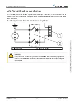
Страница 15: ...t connector The following illustration shows the circuit breaker wiring scheme 1 Power input 2 Circuit breaker CAUTION The installation must comply with the standard IEC 60364 Installing appropriate f...

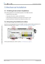
Страница 16: ...in 0 50 C l Keep the aluminum controller frame temperature within 0 65 C 5 2 Mounting the OEM Control Box Use the four mounting brackets to mount the OEM Control Box see the following illustration For...

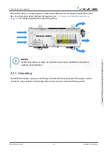
Страница 17: ...e airflow NOTICE Insufficient airflow or warm air circulation can cause the OEM Control Box to overheat and shut down 5 2 1 Grounding The OEM Control Box casing is electrically connected to the ground...

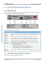
Страница 18: ...d Ethernet Connect external devices supporting MODBUS Ethernet IP or PROFINET USB ports Connect USB devices for example a mouse keyboard a USB flash drive Mini DisplayPort Connect a monitor The output...

Страница 19: ...Robot Arm brakes engage 2 Press Re Initialize to clear the fault state and power on the Teach Pendant 3 Once the Teach Pendant is restarted exit the start up screen 4 In the Header tap Installation an...

Страница 20: ...bots com support 6 2 Setting up Remote ON OFF Control and Emergency Stop The OEM Control Box requires a remote ON OFF control and an emergency stop pushbutton The following sections describe how to in...

Страница 21: ...he Control Box The following illustration shows the minimum required Emergency Stop installation NOTE For more information refer to the robot User Manual available on the support website l https www u...

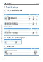
Страница 22: ...rol Box DC Property Min Max Unit Input Voltage 24 48 19 72 VDC Stand by Power 7 W Power consumption average UR3e 300 W Power consumption average UR5e 570 W Power consumption average UR10e 615 W 7 2 Co...

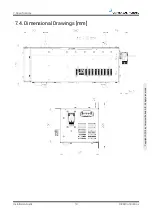
Страница 23: ...7 4 Dimensional Drawings mm Installation Guide 19 OEM Control Box 7 Specifications Copyright 2019 by Universal Robots A S All rights reserved...

Страница 24: ...e is wired correctly see 4 3 Power Source Wiring on page 9 l Ensure that the DC source connection polarity is correct Reverse polarity causes permanent damage to the OEM Control Box The Control Box tu...

Страница 25: ...nd improvement 9 3 Declarations According to EU directives Universal Robots robots are certified according to the following directives l 2006 42 EC Machinery Directive MD According to the Machinery Di...

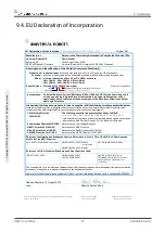
Страница 26: ...eted machine fulfils all applicable Directives and update the harmonized and other standards I Machinery Directive 2006 42 EC The following essential requirements have been fulfilled 1 1 2 1 1 3 1 1 5...

Страница 27: ...tent permitted by law Customer shall be solely responsible for complying with and shall otherwise assume all liabilities that may be imposed in connection with any legal requirements adopted by any go...

Отзывы: