V200-18-E5B
S n a p - i n I / O M o d u l e
3/05
6
Unitronics
Changing Jumper Settings
To access the jumpers, you must remove the snap-in I/O module from the controller, and then remove the
module’s PCB board. Before you begin, turn off the power supply, disconnect and dismount the controller.
Before performing these actions, touch a grounded object to discharge any
electrostatic charge.
Avoid touching the PCB board directly by holding the PCB board by its connectors.
Accessing the Jumpers
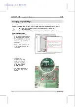
First, remove the snap-in module.
1. Locate the 4 buttons on the sides
of the module, two on either side.
Press the 2 buttons on either side
of the module as shown, and hold
them down to open the locking
mechanism.
2. Gently rock the module from side
to side, easing the module from
the controller.
3. Using a Philips
screwdriver, remove the
center screw, shown in
the figure below, from
the module’s upper PCB
board.
Do not remove
any other screws
.
4. Holding the PCB board by its
edges, gently lift it out of the
module.
i4 Automation Ltd - 01480 395256

