Unitek P3 60 Скачать руководство пользователя страница 25

Warranty 


Classic P3 60-150 A 

                                   01/2018 - V1


24 

Er

ro

r d

iag

no

sis


8


Warranty 


UNITEK

 warranties that the device is free from material and production defects. Test results are 

recorded and archived with the serial number. 


The warranty time begins from the time the device is shipped, and lasts two years.  


UNITEK

 undertakes no warranties for devices which have been modified for special applications. 


During the warranty period, 

UNITEK 

will, at its option, either repair or replace products that prove 

to be defective, this includes guaranteed functional attributes. 

UNITEK

 specifically disclaims the 

implied warranties or merchantability and fitness for a particular purpose. For warranty service or 

repair, this product must be returned to a service facility designated by 

UNITEK


For products returned to UNITEK for warranty service, the buyer shall prepay shipping charges to 

UNITEK

 and 

UNITEK 

shall pay shipping charges to return the product to the buyer. 


However, the buyer shall pay all shipping charges, duties and taxes for products returned to 

UNITEK

 from another country. 


The foregoing warranty shall not apply to defects resulting from: 

- improper or inadequate repairs effected by the buyer or a third party, 

- non-observance of the manual which is included in all consignments, 

- non-observance of the electrical standards and regulations, 

- improper maintenance 

- acts of nature. 


All further claims on transformation, diminution and replacement of any kind of damage, 

especially damage, which does not affect the UNITEK device, cannot be considered. Follow-on 

damage within the machine or system, which may arise due to malfunction or defect in the device 

cannot be claimed. This limitation does not affect the product liability laws as applied in the place 

of manufacture (i.e. Germany). 


UNITEK

 reserves the right to change any information included this MANUAL. 

All connection circuitry described is meant for general information purposes and is not 

mandatory. 

The local legal regulations, and those of the standards authorities have to be adhered to. 

UNITEK 

does not assume any liability, expressively or inherently, for the information contained in this 

MANUAL, for the functioning of the device or its suitability for any specific application. 


All rights are reserved. 

Copying, modifying and translations lie outside 

UNITEK’s 

liability and thus are not prohibited.  


UNITEK’s 

products are not authorised for use as critical components in the life support devices or 

systems without express written approval. 

The onus is on the reader to verify that the information here is current


Содержание P3 60

Страница 1: ...1 Quadranten Classic P3 60 150 A Industrie Elektronik G m b H Hans Paul Kaysser Stra e 1 71397 Leutenbach Nellmersbach Issue Revision Tel 07195 92 83 0 Fax 07195 92 83 129 info unitek online de www un...

Страница 2: ...faces 6 3 Mechanical Installation 7 3 1 Dimension 7 3 2 Dimension 8 4 Electrical installation 9 4 1 Connection 9 4 2 Connection diagram 11 4 3 CE Advices 12 4 4 Motor connection 13 4 5 Actual value co...

Страница 3: ...of power flow in electrical power systems Protection rating IP00 Control and power connections can voltage lead works without the drive Measured before disassembly voltage 2 2 Standards and guideline...

Страница 4: ...ealth and safety guidelines Adjustments and programming should only be carried out by suitable trained personnel with knowledge in electronic drives and their software should only be carried out in ac...

Страница 5: ...e control electronics The distance of air gaps and leakage paths adhere to the VDE standards 8mm Components fully insulated thyristor modules comfortably over dimensioned only components customary in...

Страница 6: ...4 2 Armature chokes are necessary only for special applications Cooling self cooling fan fan Dimensions wxhxd mm 290x210x170 290x210x170 290x210x170 P3 500 550 x Power connection 500 550V Auxiliary vo...

Страница 7: ...loop circuit Control precision 2 Control range 1 50 Speed control loop circuit with REG Control precision without actual value error 0 1 Control range 1 300 2 6 Interfaces Function Connector no 24Volt...

Страница 8: ...Current control loop RVI LED displays Enable Current control loop enable green enabled Triggering enable Z green enabled Current command value Current control loop RVI RVI green control active The lum...

Страница 9: ...Mechanical Installation Classic P3 60 150 A 01 2018 V1 8 Dimension 3 2 Dimension Manuals Zeichnungen E P3 M1352...

Страница 10: ...e plate Current consumption 0 1A Fuse F1 0 8A 5x20 Manuals Zeichnungen P3 A054 Hilfssp The auxiliary voltage and the field supply are both connected across the plug in terminal X5 The phase position o...

Страница 11: ...ltage steadiness isolating transformers must be used The transformer performance is determined by the permanent current and the secondary voltage Fast acting fuses must be installed between the transf...

Страница 12: ...11 01 2018 V1 Classic P3 60 150 A Electrical installation Connection diagram 4 2 Connection diagram Manuals Zeichnungen E P3 A021...

Страница 13: ...ound using a 10mm wire The motor housing must be connected to ground using a 10mm wire The device ground X1 8 must be connected to the mounting plate using a 2 5mm wire Device PE screw must be connect...

Страница 14: ...e the fuse to fail RNB resistors brake resistors in case of power supply failure are to be connected in parallel directly to the motor armature without isolating the motor from the control unit Zeichn...

Страница 15: ...est results can be achieved through the use of dc tacho generators Three phase tacho generators with rotor position evaluation or digital actual value encoders as well as ac or three phase tachos with...

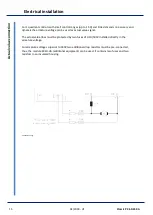
Страница 16: ...armature voltage can be used as actual value signal The actual value lines must be protected by two fuses of 0 1A 500V installed directly in the armature voltage For armature voltages superior to 180V...

Страница 17: ...st armature circuit inductance For a higher inductance the proportional amplification can be changed via the contacts 1 and 2 and the integral time constant can be changed via the contacts 3 and 4 Osc...

Страница 18: ...17 01 2018 V1 Classic P3 60 150 A Adjustment Circuit diagram 5 2 Circuit diagram Manuals Zeichnungen E P3 S074 1...

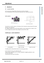
Страница 19: ...s of measuring instruments which indicate mean values or by instruments which indicate actual values When measuring the dc current with these different measuring instruments there will be measuring er...

Страница 20: ...tch S5 to position 6 Adjust the potentiometer Imax1 to left full scale Adjust the potentiometer Imax2 to approx 10 Potentiometer Xp to 50 Potentiometer ID 100 Potentiometer IxR left full scale Potenti...

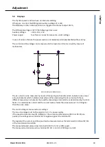
Страница 21: ...witch S5 large centrifugal mass high adjusted value small centrifugal mass low adjusted value With the command value set to 10 speed increase the amplification by turning the potentiometer Xp clockwis...

Страница 22: ...e Imax1 extern Voltage V no function Current nom value Imax2 extern Voltage V Speed controll settings REGxx Switches Tacho adjustment S9 Position REG5 Schotax 1 P term S4 Position I term S5 Position D...

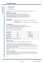
Страница 23: ...OFF Measuring value Armature voltage max V Armature current peak A Armature current steady A Tachometer voltage max V Acceleration X4 16 V ms Integrator X4 14 V ms Motor data Identification name plate...

Страница 24: ...value Tacho armature voltage Values of the tacho switch S9 too low Command value too high For armature voltage control Field current too low Fuses armature voltage feedback activated Motor runs unste...

Страница 25: ...buyer or a third party non observance of the manual which is included in all consignments non observance of the electrical standards and regulations improper maintenance acts of nature All further cl...

Отзывы: