


68
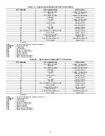
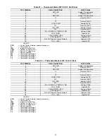
Table 25 — RTU Open Controller Inputs and Outputs
LEGEND
(1)Safety Chain Feedback: 24Vac required at this terminal to provide
“Run Enable” status. See Input/Output section for additional instruc-
tions.
(2)These inputs are configurable. If installed, they take the place of
the default input on the specific channel. See appropriate Input Con-
figuration Section for wiring and setup instructions.
(3)Parallel pins J5—1 = J2—6, J5—3 = J1—10, J5—5 = J1—2 are
used for field installation.
(4)Refer to the input configuration and accessory sections of the
RTU Open Multi-Protocol Controller Controls, Start-Up, Operation
and Troubleshooting manual for more detail.
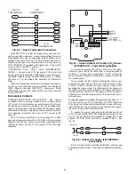
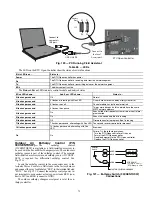
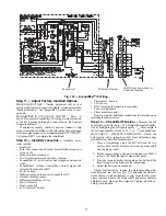
The RTU Open controller requires the use of a Carrier space
sensor. A standard thermostat cannot be used with the RTU
Open system.
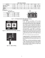
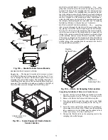
SUPPLY AIR TEMPERATURE (SAT) SENSOR — On
FIOP-equipped 50TC unit, the unit is supplied with a supply-
air temperature (SAT) sensor (33ZCSENSAT). This sensor is a
tubular probe type, approx 6-inches (152 mm) in length. It is a
nominal 10k ohm thermistor.
The SAT is factory-wired. The SAT probe is wire-tied to the
supply-air opening (on the horizontal opening end) in its ship-
ping position. Remove the sensor for installation. Re-position
the sensor in the flange of the supply-air opening or in the sup-
ply air duct (as required by local codes). Drill or punch a
1
/
2
-in. hole in the flange or duct. Use two field-supplied, self-
drilling screws to secure the sensor probe in a horizontal orien-
tation. See Fig. 76.
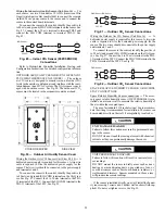
OUTDOOR AIR TEMPERATURE (OAT) SENSOR —
The OAT is factory-mounted in the EconoMi$er2 (FIOP or
accessory). It is a nominal 10k ohm thermistor attached to an
eyelet mounting ring.
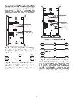
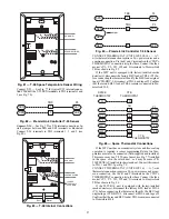
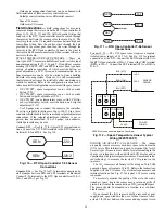
ECONOMI$ER2 — The RTU Open controller is used with
EconoMi$er2 (factory-installed option or field-installed acces-
sory) for outdoor air management. The damper position is con-
trolled directly by the RTU Open controller; EconoMi$er2 has
no internal logic device.
POINT NAME
BACNET OBJECT
NAME
TYPE OF I/O
CONNECTION PIN
NUMBER(S)
CHANNEL DESIGNATION
DEDICATED INPUTS
Space Temp / Zone Temp
zone_temp
AI (10K Thermistor)
J20—1 & 2
Analog Input 10
Supply Air Temperature
sa_temp
AI (10K Thermistor)
J2—1 & 2
Analog Input 6
Outside Air Temperature
oa_temp
AI (10K Thermistor)
J2—3 & 4
Analog Input 7
Space Temperature Offset Pot
stpt_adj_offset
AI (100K Potentiometer)
J20—3 & 4
Analog Input 11
Safety Chain Feedback
safety_status
BI (24 VAC)
J1—9
Binary Input 4
Compressor Safety Status (1)
comp_status
BI (24 VAC)
J1—2
Binary Input 3
Fire Shutdown Status
firedown_status
BI (24 VAC)
J1—10
Binary Input 5
Enthalpy Status
enthalpy_status
BI (24 VAC)
J2—6 & 7
Binary Input 8
Humidistat Input Status
humstat_status
BI (24 VAC)
J5—7 & 8
Binary Input 9
Zone Temperature
N/A
N/A
J13—1—4
Rnet
CONFIGURABLE INPUTS(4)
Indoor Air CO
2
iaq
AI (4-20 mA)
J4—2 & 3 or J4—5 & 6
Analog Input 2
Outdoor Air CO
2
oaq
AI (4-20 mA)
Analog Input 1
Space Relative Humidity
space_rh
AI (4-20 mA)
Analog Input 10
Supply Fan Status (2)
sfan_status
BI (24 VAC)
J5—1 & 2 or J5—3 & 4,
J5—5 & 6 or J5—7 & 8 (3)
Binary Input 3, 5, 8, or 9, except
where intrinsic input is used
Filter Status (2)
filter_status
BI (24 VAC)
Binary Input 3, 5, 8, or 9, except
where intrinsic input is used
Door Contact (2)
door_contact_status BI (24 VAC)
Binary Input 3, 5, 8, or 9, except
where intrinsic input is used
Remote Occupancy input (2)
occ_contact_status
BI (24 VAC)
Binary Input 3, 5, 8, or 9, except
where intrinsic input is used
IGC input (2)
igcovr_status
BI (24 VAC)
Binary Input 9. Mandatory input
on gas heat units.
OUTPUTS
Economizer Output
econ_output
AO (4-0mA)
J2—5
Analog Output 1
Supply Fan VFD
vfd_output
AO (2-10Vdc)
J22—1 & 2
Analog Output 2
Supply Fan Relay
sfan
BO Relay (24VAC, 1A)
J1—4
Binary Output 1 (G)
Cool 1 Relay State
comp_1
BO Relay (24VAC, 1A)
J1—8
Binary Output 5 (Y1)
Cool 2 Relay State
comp_2
BO Relay (24VAC, 1A)
J1— 7
Binary Output 4 (Y2)
Cool 3 Relay State
comp_3
BO Relay (24VAC, 1A)
J11—5 & 6
Binary Output 7 (Y3)
Heat 1 Relay State
heat_1
BO Relay (24VAC, 1A)
J1—6
Binary Output 3 (W1)
Heat 2 Relay State
heat_2
BO Relay (24VAC, 1A)
J1—5
Binary Output 2 (W2)
Power Exhaust Relay State
pexh
BO Relay (24VAC, 1A)
J11—2 & 3 (N.O.)
Binary Output 8 (PE)
Dehumidification Relay
dehum
BO Relay (24VAC, 1A)
J11—7 & 8 (N.O.)
Binary Output 6
AI
—
Analog Input
AO
—
Analog Output
BI
—
Binary Input
BO
—
Binary Output
Содержание Carrier WeatherMaker 50TC A08 Series
Страница 4: ...4 Fig 2 Unit Dimensional Drawing Size 08 09 12 Units...
Страница 5: ...5 Fig 2 Unit Dimensional Drawing Size 08 09 12 Units cont...
Страница 6: ...6 Fig 3 Unit Dimensional Drawing Size 14 Unit...
Страница 7: ...7 Fig 3 Unit Dimensional Drawing Size 14 Unit cont...
Страница 9: ...9 Fig 4 Unit Dimensional Drawing Size 16 Unit cont...
Страница 13: ...13 Fig 8 Roof Curb Details Size 16 Unit...
Страница 33: ...33 Fig 62 Typical Humidi MiZer Adaptive Dehumidification System Humidistat Wiring 50TC 08 14 Unit Sizes...
Страница 34: ...34 Fig 63 Typical Humidi MiZer Adaptive Dehumidification System Humidistat Wiring 50TC 16 Unit Sizes HUMIDISTAT...
Страница 50: ...50 Fig 73 50TC 16 Control Box Component PremierLink Locations...
Страница 51: ...51 Fig 74 Typical PremierLink Control Wiring Diagram...
Страница 52: ...52 Fig 75 Typical PremierLink Control Wiring Diagram with Humidi MiZer System Option...
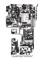
Страница 64: ...64 Fig 106 Typical RTU Open Controller Wiring Diagram 50TC 08 14 Size Units...
Страница 65: ...65 Fig 107 Typical RTU Open Controller Wiring Diagram 50TC 16 Size Unit...
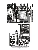
Страница 66: ...66 Fig 108 Typical RTU Open Controller Wiring Diagram with Humidi MiZer System Option 50TC 08 14 Size Units...
Страница 67: ...67 Fig 109 Typical RTU Open Controller Wiring Diagram with Humidi MiZer System Option 50TC 16 Size Units...


