


5
2
CONNECTION
5
CONNECTION
Chapter
2
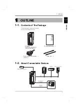
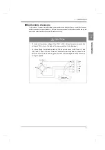
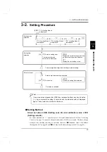
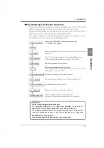
2-2.
Load Cell Connection
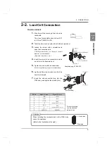
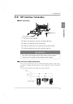
How to connect
1.
Strip 5mm of the covering of the wire to be
connected.
The size of connectable wires is from 0.21
to 3.31mm
2
(AWG12 to 24).
2.
Twist the tip to such an extent that it will not spread out.
3.
Loosen the screw with a screwdriver to
open the connection hole.
A Phillips screwdriver 3 to 3.5mm #1 in shaft
diameter is recommended.
(Precision screwdriver, etc.)
4.
Insert the wire into the connection hole so
as not to let the tip spread out.
5.
Tighten the screw with the screwdriver.
0.5Nm of tightening torque is recommended.
6.
Lightly pull the wire to make sure that it is
securely clamped.
7.
Insert the wire-connected plug into the
F160 body, and tighten the screws (two).
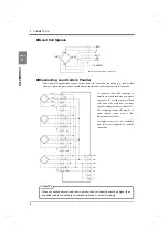
Pin No.
Signal (6-wire)
Signal (4-wire)
* For short-circuiting,
use the attached
jumper wires.
1
+SIG
+SIG
2
-SIG
-SIG
3
+EXC
+EXC
(Short-circuit
*
3 to 4)
4
+S
5
-EXC
-EXC
(Short-circuit
*
5 to 6)
6
-S
7
SHIELD
SHIELD
5mm
Adaptable plug: ETB42-07P
Tighten
(Turn clockwise.)
Tighten
(Turn clockwise.)
When installing the terminal block to the F160 body,
check its orientation.
(Refer to the illustration at the right.)
Attention
Insert side
Right side
Содержание F160
Страница 1: ...01AUG2017REV 1 06 WEIGHING CONTROLLER F160 CC Link Ver 1 10 OPERATION MANUAL...
Страница 9: ...CONTENTS VIII CONTENTS VIII M E M O...
Страница 84: ...75 8 SPECIFICATIONS 75 SPECIFICATIONS Chapter 8 Equipped with BCD parallel data output interface option Unit mm...
Страница 85: ...76 8 SPECIFICATIONS 76 SPECIFICATIONS Chapter 8 Equipped with CC Link interface option Unit mm...
Страница 99: ......