9
2
INSTALLATION AND CONNECTION
9
INSTALLAT
ION AND CONNECTION
Chapter
2
2-1.
Installation
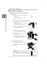
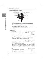
To install the F381A into a control panel, use the following procedure.
1.
Make a hole in the panel according to the
panel-cut dimensions.
2.
Remove the screws (two), and remove the
guide rails from both sides.
* Do not use other screws than those installed
to the F381A body.
3.
Fit in the F381A from the front of the panel.
4.
Install from the rear the guide rails having
been removed from both sides in Step 2,
and fix them with the screws (two).
2
INSTALLATION AND CONNECTION
92mm
Panel-cut
+1
0
–
Panel thickness
1.6 to 3.2mm
dimensions
92mm
+1
0
–
Guide rail
Guide rail
Screws
Содержание DeviceNet F381A
Страница 1: ...15APR2013REV 3 10 DYNAMIC FORCE PROCESSOR F381A OPERATION MANUAL ...
Страница 9: ...Contents VIII Contents VIII M E M O ...
Страница 34: ...25 2 INSTALLATION AND CONNECTION 25 INSTALLATION AND CONNECTION Chapter 2 M E M O ...
Страница 147: ...138 8 SPECIFICATIONS 138 SPECIFICATIONS Chapter 8 8 2 Outside dimensions Unit mm ...
Страница 164: ......

